GMP 89009 Manuale

Page 1 of 16 General Machine Products Co., Inc.
Copyright 2013 by General Machine Products Co., Inc
All rights reserved. No part of this publication may be copied, reproduced or transmitted in any form
whatsoever without the written permission of General Machine Products Co., Inc.
Compressor Aftercooler
OPERATION & MAINTENANCE MANUAL
GMP • 3111 Old Lincoln Hwy • Trevose, PA 19053 • USA
TEL: +1-215-357-5500 • FAX: +1-215-357-6216 • www.gmptools.com
SEP 2013 USA Ver 1
Manual P/N 29536
Model 89009

Page 2 of 16 General Machine Products Co., Inc.
REVISION HISTORY
Rev # Date Details Author
01 09/09 Original Issue A Miller
02 03/12 Updated L Kilpin
03 09/13 US Version 1 A Konschak

Page 3 of 16 General Machine Products Co., Inc.
CONTENTS
1. Safety Instructions
2. General Description
3. Specification
4. Operating Procedure
5. Maintenance and servicing
6. Spare Parts
7. Layout of equipment
APPENDICES
Appendix 1 General arrangement drawing C-1227-AS1001
Warranty
Page 4 of 16 General Machine Products Co., Inc.
1. SAFETY INSTRUCTIONS
THIS EQUIPMENT MUST ONLY BE USED BY AUTHORISED PERSONNEL,
WHO HAVE BEEN SUITABLY TRAINED AND COMPETENT TO DO SO.
THESE INSTRUCTIONS ARE TO BE MADE AVAILABLE TO OPERATORS
OF THIS EQUIPMENT AT ALL TIMES, FAILURE TO OBSERVE THESE
SAFETY INSTRUCTIONS COULD RESULT IN SERIOUS PERSONAL INJURY
AND / OR PROPERTY DAMAGE.
WORK AREA AND GENERAL SAFETY
1) Read and understand the operation and maintenance manual supplied with
this equipment. Keep it in a convenient place for future reference.
2) Keep children and untrained personnel away from this equipment while in op-
eration.
3) Keep all guards and safety devices in place. Do not operate this equipment
with guards removed or damaged.
4) Keep hands, feet and loose clothing away from moving parts.
5) Always stop the machine to carry out lubrication and servicing.
6) Check machine before starting for worn or damaged parts. Check that all nuts
and bolts are tight.
7) If machine is left unattended, ensure that unauthorized use is prevented.
8) Never leave the machine unattended while in use.
9) Consider the use of safety barriers, especially when used in public places.
10) Beware of hot surfaces.
11) Some component and assembly parts are in excess of 25kg (55lb). When
lifting care must be taken, ensure sufficient man power/lifting gear is available,
to prevent personal injury and damage to the machine.
12) Waste oils/water are to be disposed of via an environmentally acceptable
method – e.g.: passed on for recycling.

Page 5 of 16 General Machine Products Co., Inc.
13) Wear ear defenders if noise levels are considered high to prevent ear dam-
age
14) The machine must be operated on firm ground.
15) Stay clear of pipes under pressure and cables or lines under tension.
16) Only use the machine for its intended purpose.
17) Avoid using the machine in air born dust environments.
18) Ensure that the compressed air hoses are connected correctly, hot air from
the compressor entering the pipe marked input, the cool air to the blowing ma-
chine to the pipe marked output.
19) Ensure that Air Hoses are laid out as straight as possible to avoid problems
when pressurized.
20) Personnel should only approach the aftercooler when in operation wearing
suitable eye and body protection.
21) Check that all the cam and groove air hose couplings are fully locked, and
the securing clips are fitted before pressurizing the air hoses.
22) Do not unlock the hose cam couplings while the aftercooler is pressurized.
23) The air pressure should not exceed 12 bar (175 P.S.I.)
24) No servicing or maintenance work is to be carried out while the aftercooler is
pressurized.
25) Before carrying out any servicing or maintenance work it is advisable to al-
low the Aftercooler to cool down.
Page 6 of 16 General Machine Products Co., Inc.
2. GENERAL DESCRIPTION
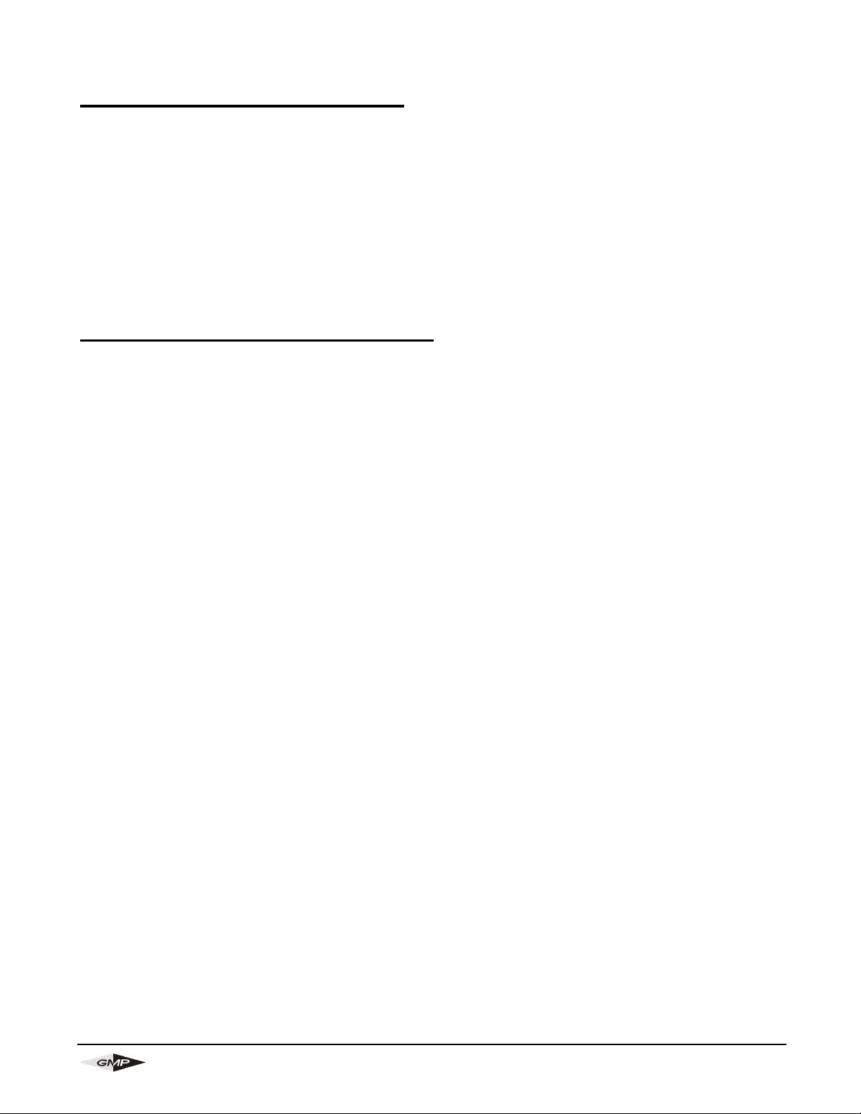
This Compressor Aftercooler has been designed to cool compressed air and re-
move water droplets prior to the air entering a GMP Tornado Cable Blowing Ma-
chine.
The Cooler unit is horizontally mounted on a tubular steel frame and is complete
with pneumatic wheels and transit handle for easy maneuverability.
An air motor driven fan forces cooling air through the Compressor Aftercooler
and reduces the temperature of the compressed air. The air motor is driven by
compressed air taken from the down stream side of the water separator and
passes through a filter-regulator-
lubricator assembly prior to entering the
air motor.
The Compressor Aftercooler is fitted
with cam action quick release air hose
couplings. Waste oil/water mixtures are
collected in a frame mounted drain can
for environmentally acceptable disposal.
The water separator protector bar dou-
bles as a carrying handle to assist with
moving the aftercooler over very soft ter-
rain or loading it into a vehicle.
GENERAL PNEUMATIC SAFETY INSTRUCTIONS
The GMP Compressor Aftercooler is a pneumatic device, using pressurized air
to project cable at high velocities. Please observe the following precautions
when operating the aftercooler: -
1) Compressed air can cause flying debris. This could cause personal injury. Al-
ways wear personal protective equipment.
2) Do not disconnect air hoses when under pressure.
3) Only authorized, fully trained personnel should operate the air compressor.

Page 7 of 16 General Machine Products Co., Inc.
3. SPECIFICATIONS
Serial No:
OPERATING CAPACITIES
Max. Working Pressure 12 BAR (175 P.S.I.)
Max. Air Compressor flow Rate 12 Cubic Meters / Minute (425 cubic fpm)
Max. Air Inlet Temperature 65 Deg. C (150 F)
Max. Air Outlet Temperature 50 Deg. C (122 F)
Max. Ambient Air Temperature 45 Deg. C (113 F)
DIMENSIONS
Length: 1135 mm (44.7”)
Height: 1000 mm (39.4”)
Width: 640 mm (25.2”)
Weight: 74 kg (163 lbs.)
Tire Size: 3.00 - 4 4ply tube tire
Tire Pressure 1.72 Bar (25 P.S.I.)
AIR HOSE CONNECTIONS
TYPE 1½” Cam and groove quick couplings
Air from Compressor Marked input
Air to Cable Blowing Machine Marked output
Air Motor Max. working Pressure 7 Bar (100 p.s.i.)
Air Motor Oil High quality air tool lubrication oil (1 drop per minute)

Page 8 of 16 General Machine Products Co., Inc.
4. OPERATING PROCEDURE
IT IS IMPERATIVE THAT ALL PERSONS USING, OPERATING OR MAIN-
TAINING THIS AFTERCOOLER BE FULLY TRAINED AND COMPETENT TO
DO SO, AND HAVE READ THE ENTIRE OPERATING MANUAL. GMP CAN-
NOT BE HELD RESPONSIBLE FOR MISUSE OF THIS EQUIPMENT.
4.1
Refer to section 5.1 for pre-usage checks.
4.2
Connect the air supply hose from the Air compressor to the aftercooler inlet us-
ing the cam and groove quick action release hose couplings, check that all the
cam and groove air hose couplings are fully locked, and the securing clips are
fitted before pressurizing the air hoses. The inlet connection on the aftercooler
from the compressor is marked input (an arrow gives the direction of com-
pressed air flow). The hose should be laid out as straight as possible to avoid
problems when pressurized. Note: Do not unlock the hose cam couplings while
the Aftercooler is pressurized.
4.3
Connect the air supply hose from the Aftercooler outlet to the cable Blowing Ma-
chine inlet using the cam and groove quick action release hose couplings, check
that all the cam and groove air hose couplings are fully locked, and the securing
clips are fitted before pressurizing the air hoses. The outlet connection on the
aftercooler to the blowing Machine is marked with output, (an arrow gives the
direction of compressed air flow). The hose should be laid out as straight as
possible to avoid problems when pressurized. Note do not unlock the hose cam
couplings while the Aftercooler is pressurized.
4.4
With the compressor running at a pressure not exceeding 12 BAR (175 P.S.I.) in
a safe condition, make sure that the pressure gauge on the filter-lubricator is
reading 7 BAR (100 P.S.I.) If it is not, adjust the knob on top of the regulator.
The regulator can be locked into position by raising the knob after adjustment.
For maximum reliability the 7 BAR (100 P.S.I.) setting should be maintained dur-
ing the blowing operation. Refer to the operator manual supplied with the air mo-
tor for further details.
Page 9 of 16 General Machine Products Co., Inc.
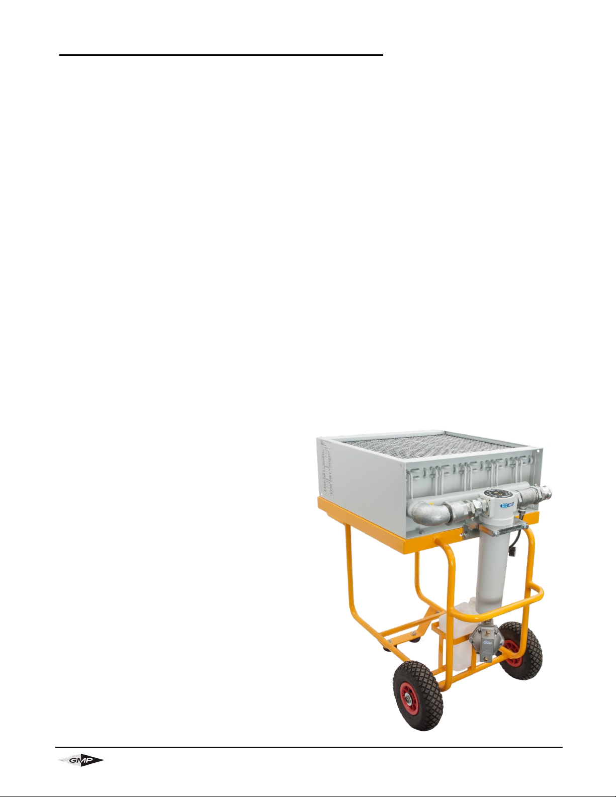
4.5
Adjust the red screw adjuster on the air motor lubricator using a 4mm hex
wrench to allow one drip of oil per minute as viewed in the oiler site dome. Air
must be on and driving fan for this adjustment. This will be almost closed.
(When set, this will not require frequent adjustment)
4.6
The aftercooler system is now available for use.
4.7
Condensate from the filters will be collected in the plastic container. Dispose of
the contents in an environmentally acceptable way for oil contaminated waste.
The can should be emptied when approximately three quarters full.
Use 4mm hex wrench for adjusting
lubrication amount
Remove oil reservoir
by turning 1/4 turn
counter-clockwise to fill
Air motor adjustment knob

Page 10 of 16 General Machine Products Co., Inc.
5.0 MAINTENANCE
IT IS IMPERATIVE THAT ALL PERSONS USING, OPERATING OR MAIN-
TAINING THIS COMPRESSOR AFTERCOOLER BE FULLY TRAINED AND
COMPETENT AND AUTHORIZED TO DO SO AND HAVE READ THE EN-
TIRE OPERATING MANUAL.
IT IS RECOMMENDED THAT THIS COMPRESSOR AFTERCOOLER IS
SERVICED EVERY 12 MONTHS, REGARDLESS OF ITS CONDITION OR
THE NUMBER OF OPERATING HOURS USED. THIS WILL HELP TO EN-
SURE RELIABLE, TROUBLE FREE SERVICE.
GMP, CANNOT BE HELD RESPONSIBLE FOR MISUSE OF THIS EQUIP-
MENT.
5.1 PRE-USAGE CHECKS
● Check that the oil reservoir on the air motor lubricator is full of a high quality
air tool lubrication oil.
● Check that the drain bowls on both the air motor filter/regulator and the after-
cooler separator are emptying correctly.
● Check that the aftercooler grill is free from dirt and leaves, if necessary blow
the debris outwards with a low pressure airline, (Max. 2 Bar 30 P.S.I.). Note,
this should be undertaken with due consideration to personnel safety. Correct
cooling depends upon an uninterrupted flow of air through the finned tubes of
the cooler. If the spaces between the fins are allowed to become clogged with
dirt, the performance of the aftercooler will deteriorate.
● Check that the cam and groove air hose coupling faces are clean and free
from debris.
● Check the tire pressure, adjust if necessary.
● Check that all screws are tight, especially the fan mounting bracket and
guard.
● Check for air leakage, rectify before commencing.
5.2 WEEKLY MAINTENANCE
● Carry out all the Pre-usage checks as per 5.1
● Open the manual discharge valve on the Condensate Separator (screw care-
fully) and let water flow out air until the compressed air will blow through for a
few seconds (into a suitable container for environmentally friendly disposal). If
a significant amount of water (more than 0.5 liters) exits the valve then the
drain must be thoroughly cleaned.
Indice


