
GRAPHTEC F-Mark Guida utente

Auto Sheet Feeder
Setup manual
User manual
Read this manual carefully before using the machine,
keep the manual in a handy place for future reference
index
1 Safety precautions
2 Main specifications
3 Dimensions
6 Accessory box
7 Cable connection
8 Overview and adjustings
9 iMark digital cutting software
10 F-Mark feeder position and push roller alignment
11 Cut the first test sheet
13 Print and cut alignment
15 Suction cups and insertion flap replacement.
16 Optical camera mounting
18 Troubleshooting

Safety Precautions
WARNING Indicates a potentially hazardous situation
which, if not avoided, could result in death
or serious injuries.
Follow these guidelines to avoid the risk of fire, burns, injury,
electric shocks, rupture, overheating, abnormal odours or smoke.
Always use the recommended AC adapter (EA10682U-120) for the
ddCutter feeder to prevent any damage or failure.
The rated voltage is 110-240V AC 50-60Hz.
Do not touch the F-Mark device during a lightning storm.
Do not use the machine / AC adapter in places of high humidity
Do not overload the power cord.
Do not place heavy objects on, or damage the power cord or plug. Do
not forcibly bend or pull the power cord.
Make sure that the plug is fully inserted in the power outlet. Do not use
an outlet that is loose.
Do not allow the machine / AC adapter / power plug to get wet for
example, by handling them with wet hands or spilling beverages onto
them.
Do not disassemble or modify the F-Mark / AC adapter.
Disconnect the AC adapter and stop using the machine if you notice
abnormal odour, heat, discolouration, deformation or anything
unusual while using it.
CAUTION Indicates a potentially hazardous situation
which, if not avoided, could result in minor
or moderate injury.
Follow these guidelines to avoid the risk of, injury, electric shocks,
or damages to the ddCutter.
When placing the F-Mark device, allow enough table space, take in
consideration the vibrations generated during operations.
Ignoring to do this might cause the product or part of it to fall out of
position, resulting in possible body injury or malfunction of the
product.
Don not use or store the product is exposed to direct sunlight, water
or oil splashes, salty air or saltwater, dust or humidity, flamable gas.
Do not touch the paper sheets duting operation, the paper edge can
cut seriously your skin.
Do not approch with your face to the moving arm and moving paper
sheets.
Do not attempt to lubricate the mechanisms.
Do not apply force or object weights on the moving arm.
Lay the power adapter in a position so the green light is visible.
This will alert if the adapter should accidentally go off due to external
effects. If for any reason the green light goes off, disconnect theAC
power cord from the wall.
Be sure to grasp the plug, not the cable, when disconnecting the
power supply from an electric socket.
1

Main specifications
The F-Mark automatic feeder is part of the CE6000plus ASF
system.
It allows automatic operations for contour cutting on printed
adhesive sheets or cardboard.
The system is composed by an automatic feeder, a cutting
plotter, a dedicated software with optical detection features and
the exit tray.Amobile lever equipped with vacuum suction cups
lifts the sheets from the inbox tray and inserts them into the
plotter.
The F-Mark feeder is equipped with an internal vacuum pump,
which does not require external air connections.
The system is connected to a computer using a USB cable,
the dedicate software must be installed on a PC running
on Windows OS.
The safety precautions and specification here are referred to
the feeder unit only.
For safety precautions and specifications of the plotter, refer
to the Graphtec CE6000plus manual.
Media size
Width : 279
~ ~
350mm
( 300 350mm with CE6000-60)
Length : 210
A3, A4, SRA3, Extended A3 (A3, A4 not usable with CE6000-60 )
~500mm up to 700mm with optional extender
SRA3, A3Extended) ( A3
Sheet capacity About 200 sheets(limit depending on paper thickness)
Max height 35mm
Sheet weight350g/m2
Power source 100V~240V (Auto switching) 50/60Hz
Power consumption 60W
WeightFeeder 10kg Exit tray 4kx
Feeding system Internal vacuum pump
Feeding time 5 sec
Media separation Air blowers, variable air stream sseparation
Win7 / Win8.x / Win10
Feeder 590(L) x 400(W) x 220(H)mm
System including exit tray:
1220(L) x 680(W) x 270(H from tabletop )mm
Extender to 700mm sheets, stopper for small formats
Temperature: 10~35°Humidity 35~75%
Temperature: 0~40°Humidity 25~75%
Tabletop 800(L)x750(W)mm
Compatible OS
Dimensions
USB
Interface
Optional parts
Operating environment
Storage environment
Installation space
2

Dimensions
59 cm
22 cm
43 cm
120 cm
82 cm 42 cm
38 cm
Choose a location that allows an easy access
to the adjusting knobs.
3
38 cm
plotter width 70~90cm
The system can be configured with a plotter
different for size and maximum cutting area:
The tabletop length to accomodate the system
is 82cm, the width varies:
CE6000plus-40 with a plotter width of 70cm
CE6000plus-60 with a plotter width of 90cm
Allow 5cm of clearance on the right and left side
to accomodate the power cord an the USB cable.
The larger plotter model does not change the
maximum size of the sheet usable on the feeder.
The larger cutting area is usable when the plotter
is used separately by the feeder.
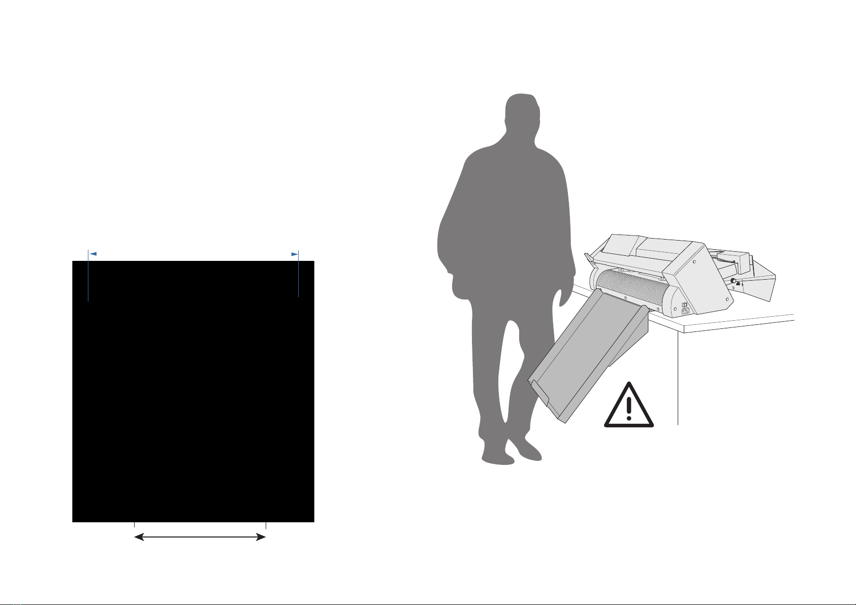
When you choose a location for the CE6000 ASF system note that
the exit tray extends for 35 cm and must be positioned in a
location free of tight passages to avoid hitting it when walking by.
4

Peel the adhesive tape on the back
of the exit tray. Press it firmly un the tabletop
The adhesive tape fix the exit tray for
a short time, it may drop if you do not
place the plotter on top.
Put the plotter on top of the exit tray
6 lines
To allow the paper to drop centrally on the
exit tray, place the plotter in order to align
the line 6 with the right edge of the exit
tray
5

Accessory box contents
Among the items on the accessory box the USB Hub is not normally necessary
it is used for troubleshooting in case of bad communicatrion betwern the computer and
the system. It may happen in case of overloaded usd port on th computer.
You have to connect the power cord to the power adapter and
the USB Hub with the miniUSB cable 1.8m long
Power adapter USB Hub power adapter
used only for
troubleshooting
USB cable 1.0m
from USB Hub to plotter
Mini USB cable 1.8m
from USB Hub to computer
USB Hub Spare suction cups
iMark software CD
Localized power cord for
power adapter
6

Cable connection
There are some USB cables and the power adapter that must be connected
before using the system.
Under the feeder there is an USB Hub fixed with a velcro tape for an easy
replacement.
The USB cable coming from inside the feeder is already connected, you
have to connect the cable from the optical camera and from the plotter.
For the CE6000-40 you can use the cable into the F-Mark accessory box.
for the CE6000-60 you have to use the USB cable from the plotter box.
The mini-USB cable goes to the computer, it is not necessary to install
drivers on the computer, you have just to wait until the system mathces the
different devices.
Depending on the computer you may have to wait few seconds up to some
minutes.
USB cable to the computer
USB cable to the plotter
USB cable to the camera
Internal USB
Bottom view
Power supply
7

Insertion Flap
Suction Cup
Side paper guide
Blower
Blowers speed
regulation knob
Main switch Rear paper guide
regulation knob
Side paper guide
adjusting knob
Magnetic Mat
Overview and adjustings
On the F-Mark there some knobs that allow some adjustment
depending on the paper size and type.
The side paper guide knob adjusts the opening of the side
giudes accordingly to the media width.
Keep the side guide loose on the media borders.
The rear paper guide knob allows to press the media on the
front of the media tray.
Keep the rear guide tigth against the sheets,
The blowers knob paper
allows to adjust the air stream of the
blowers.
Aproper setting of the blowers speed helps the paper separation,
for adhesive media keep it at minimum or turn the blower off
forcing the knob counterclockwise.
For porous paper you may test different air stream levels, turns
the knob clockwise to increase the air stream. As a rule of the
thumb use a low air stream for curled prints and an higher level for
flat prints.
From the side view you can see Vacuum adjusting knob.
You can turn it clockwise to increase the vacuum force in case
the suction cup does not pick up the sheets.
Turn it counterclockwise when using thin paper and the suction
cups pick up more than one sheet.
To return to the default position turn the knob all clockwise and
then return back counterclockwise for two turns.
8

i-Mark Digital Cutting Software
This software has been designed to manage the automation of the cutting process.
There are specic functions to execute kiss cutting, die cutting and creasing simulation.
It allows users to import graphics les in AI and EPS format.
The graphics have to contain two reference marks.
The dedicated video camera connected to the software, detects the crop mark in a fraction of a
second and adapts the cut path to the inclination and distortion of the print.
The software runs with the operating systems Windows 7, 8, 10.
Most of old Windows Seven and XP computers can be used, but not all of them.
The system is connected to the computer through a USB port.
Installation of the Graphtec driver
DO NOT INSTALL THE GRAPHTEC DRIVER !
You only have to install the driver if you want to install the other software supplied with the
plotter.
In this case, before you connect the plotter to the computer, you have to install the plotter driver
contained in the CD.
Inside the CD le <<Ce6000 drivers>> there are two version of the driver, one for Windows 32bit
and one for Windows 64bit.
Install the version related to your computer, most of the new computers are 64bit, to verify you
must open the computer icon on the desktop.
Select on the menu <<System's propriety>> to visualize the system characteristics.
Installation of the i-Mark software
Execute the installation's program imark-setup contained in the installation CD.
The setup program requires various conrmations for the installation of the software.
On some computers you could be asked the system administrator password to execute the
installation, in case you do not have this information, contact the technician who administrates
the system.
During the installation, the i-Mark program icon is created on the desktop and a shortcut in
the Windows Start Menu.
At the end of the install process you can launch the i-Mark software.
9
Altri manuali per F-Mark
2
Indice


