Green Speed Anura Manuale utente

manual
2
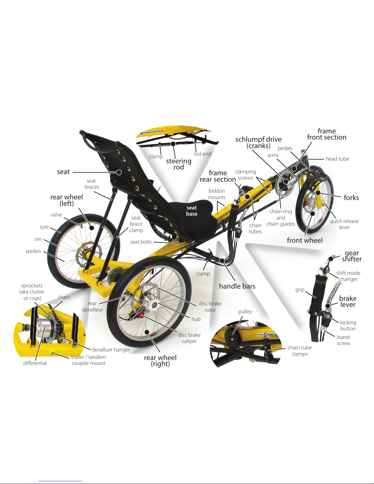
trike anatomy
2
3
4
5
6
7
8
9
10
11
12
13
14
15
3
tricycle anatomy
design
tools
fitting your differential
fitting disc brake calipers
fitting your frame together
fitting your rear wheels
fitting your front wheel
fitting your seat
adjusting your seat angle
adjusting your handle bars
fitting your pedals
adjusting to your leg length
check derailleur cables
fitting your chain
adjusting chain length
joining your chain
attaching the steering rod
aligning your steering
attaching the front brake
final check
adjusting your gears
~ front derailleur
~ rear derailleur
steering, braking,
using your gears
1st ride, stamina, pedals
tools to have while riding
maintenance, chain,
tyre pressure
accessories, warranty,
community, resources
contents
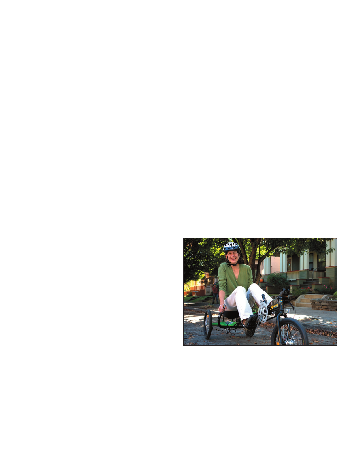
Congratulations on your purchase of a Greenspeed Anura
trike. We believe that you have purchased the finest recumbent
tricycle available in the world today. It is also our belief that
the present level of motorised transport on this small planet is
not sustainable, in environmental and social terms. Thus your
Greenspeed has been designed for everyday use, whether it be
shopping, commuting, touring the world, rehabilitation or just
exercising and having fun! With care, it should last a lifetime.
Included in this manual are instructions on how to assemble,
maintain and get the most from your Anura.
The Anura is designed to be enjoyable to ride. The high seat
with one wheel at the front & two rear, make it easy to mount
& dismount. The high seat also gives a good view in traffic. The
ergonomic placement of the handlebars, and the attention paid
to the steering geometry means that it is effortless to steer.
The three wheel disc brakes give very powerful braking. The
combination of the Schlumpf speed drive & nine speed bar
shifter allows two speed shifting while stationary or under way
and easy shifting while riding.
The differential gives a balanced drive to both rear wheels
which enables it to turn easily in both directions, and track in a
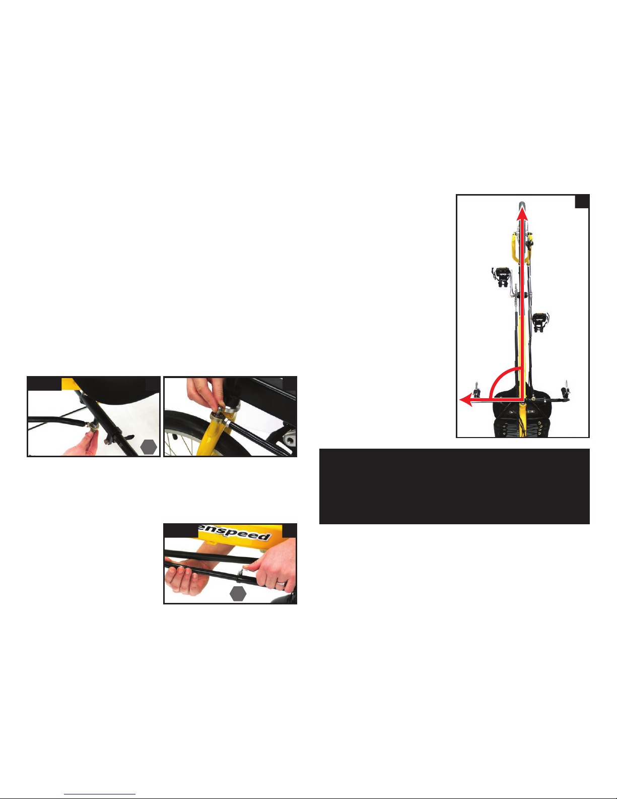
straight line up steep hills. Finally, at the end of your trip, the
trike will go through a standard doorway and park vertically,
taking up little space.
A boss welded through the rear axle brace provides an
attachment point for attaching a trailer or another Anura with
special hitches available from your Greenspeed Dealer.
designwelcome to the family
a s s e m b l y
r i d i n g
w h a t ’ s n e x t
42
56
8
15
10
4
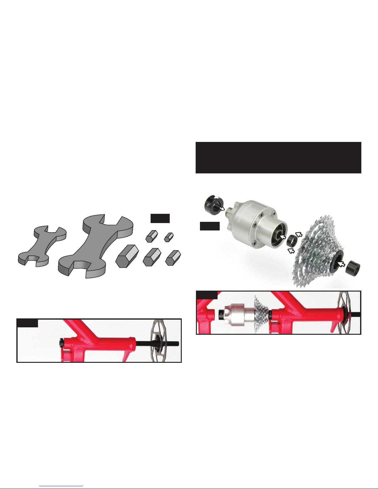
tools
Wrenches
Allen keys
fig 1
In the majority of cases your dealer will have fully assembled,
test ridden and adjusted your Anura for you. However, having an
understanding of how your Anura goes together is important and
also gives you more confidence making future adjustments.
If you are assembling from a boxed state, you start by unpacking
it all carefully. Once all the packaging has been removed, the fun
bit begins.
assembly
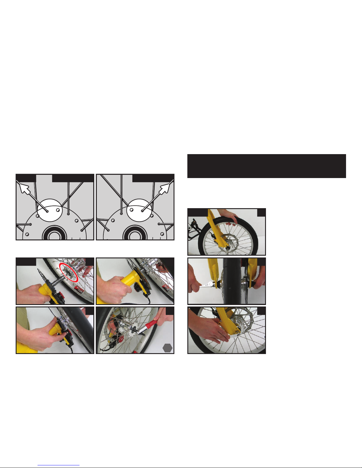
The differential (diff) is a very simple set up; collars holds each
of the the two axles in place in the frame with the diff unit in the
center with a 3rd collar holding that in the correct place.
fitting your differential
Here are the tools you will
need for the job.
in place. Undo the collar and slide it off the axle, thread the
axle through the bearing just far enough to sit the collar (step
towards bearing) onto the splined part of the axle (fig 2a).
Note: The two axle collars have a step on one side of the
collar. Orientate the step so that it sits up against the bearing.
This way the collar will not rub against the stationary part of
the bearing.
fig 2b
Now
you can fit the
cluster on by sliding the
freebody into the diff and placing
the cluster spacer (z) inside it.
Now we assemble the diff parts together (fig 2b). Check the big
collar (x) is sitting on the left hand (fatter) side of the
diff, and the black cluster spacer (y) is on the
right hand side, pressed onto the
axle receiver.
Now holding your diff/cluster assembly into position, slide the
RH axle into the diff’s axle receiver (fig 2c). You need to slide the
axle right in until the rotor mount is pressing up against the outer
bearing. Then slide the collar up against the inside bearing and
lock it in place with the grub screw.
First we’ll sit the right hand axle (the longer of the two) loosely
fig 2a
fig 2c
x
y
z
5
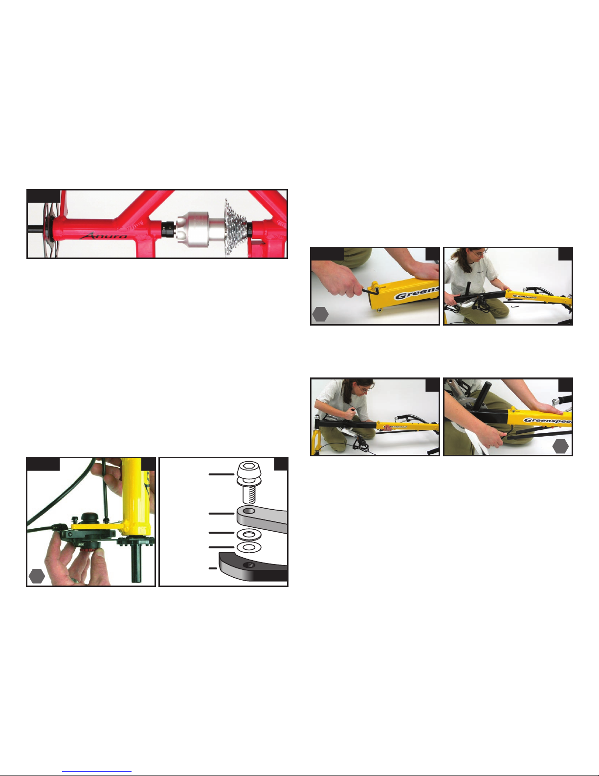
Next install your calipers onto the frame. Slide the calipers onto
the disc brake rotor and use the screws and washers to tighten
them into place (fig 3a and b).
Anura has been designed to take one washer between the frame
mount and caliper bracket, however in some cases an extra spacer
may be needed (fig 3b).
fig 3 a
fitting your disc brake calipers
Mate the front section (with the forks & cranks) to the rear
section (with the triangle shape welded into it).
fitting your frame together
fig 4 ab
cd
Slide the front section about ½ way in & tighten the two ALLEN
screws to hold it in place during assembly (fig 4c and d).
Loosen the screws (fig 4a). Take care not to disturb the shims
inside the rear section when sliding the front section into the
rear. Starting on an angle (fig 4b) makes things a little easier.
5
6
6
Now slide your Left hand axle through the two frame bearings,
the collar (step towards the bearing), and into the diff. Push it
all the way in until the rotor receiver butts up against the outer
bearing. Then slide the collar against the bearing and lock it in
place with the grub screw.
Last step is slide the diff’s large collar again the Left hand axle’s
collar and lock this into position with the grub screw.
screw
washer
frame
mount
spacer
(if needed)
caliper
bracket
b
fig 2d
6
fitting your rear wheels
Outside spoke points to the left
Left hand wheel
Outside spoke points to the right
Right hand wheel
Remove the axle screw (some models also have a cap here)
from the end of the axle. Face the hub’s retaining pins inwards
towards the rotor (fig 6a circle) and slide the wheel onto the axle
(fig 6b). Engage the pins or Allen screw heads in the holes in the
disc mounting plate (fig 6c), and then put the axle screw (and
cap if you have them) back in and tighten it.
Now fit the skewer to the axle of the front wheel if it is not
already fitted.
Unscrew the nut & slide it
through the axle from the
opposite side to the disc, then
screw the nut on until the end
of the nut is flush with the
end of the skewer.
Then fit the front wheel by
carefully sliding the disc into
the brake caliper, and the axle
into the dropouts (fig 7a).
Tighten the skewer nut finger
tight with the quick release
lever straight out (fig 7b).
Then turn the lever back to
lock the front wheel in place
(fig 7c). This should feel firm.
If the lever is not locked
firmly, release it and tighten
the nut some more until it
locks firmly into place. Inflate
the tyres to say 70 psi.
fitting your front wheel
fig 6
cd
a b
fig 7
b
a
c
fig 5 left wheel right wheel
Now install the rear wheels. Fig 5 shows that there are left and
right wheels. They can be identified by looking at the top of the
hub and following the outside spoke (that is the straight part of the
spoke is on the outside of the hub’s flange) to the left or right. Be
sure to try and install them this way in the future to increase spoke
life.
Note: It may be necessary to try different positions in fitting
the pins into the disc plate, to get them to mate properly and
go all the way in.
6
7
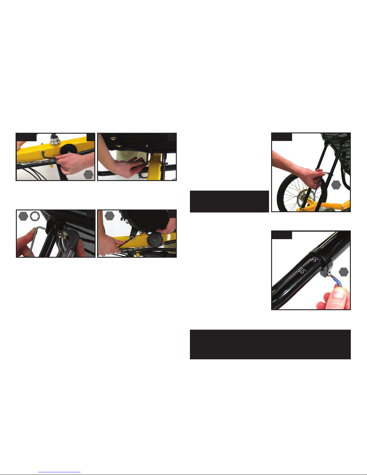
fitting your seat
Take out the two allen key screws from the frame (fig 8a) and
use them attach the seat (fig 8b), do them just snug for now, we
will tighten them later. Use the lower holes in the tag.
fig 8 a b
adjusting
your handle
bars
Loosen the clamp on the
handlebars and adjust them
to a comfortable position
making sure both bars are
parallel.
Making further adjustments to the bars later on as you tune
them for comfort will not effect your steering.
fig 10
Then fit the rear seat stays with the Allen screws & nuts (fig 8c).
If your seat angle looks okay, tighten the frame screws (fig 8d).
c d
adjusting your seat angle
4
6
46
10
Note: your handle bars need to be done up fairly tight to
prevent unnecessary movement. Some movement under duress
is acceptable in case of an accident, but they should NOT be
used for leverage in getting on or off, or in pedaling.
fig 9
To adjust the angle of your seat,
loosen the two frame screws
one turn (fig 8d), and loosen
both of the seat brace’s clamps
(fig 9). Now you can slide the
seat angle fore and aft to your
desired angle. Then tighten the
clamps back up again.
Note: Make sure you have at
least 2” (54mm) of the upper
tubes into the lower tubes.
3
8
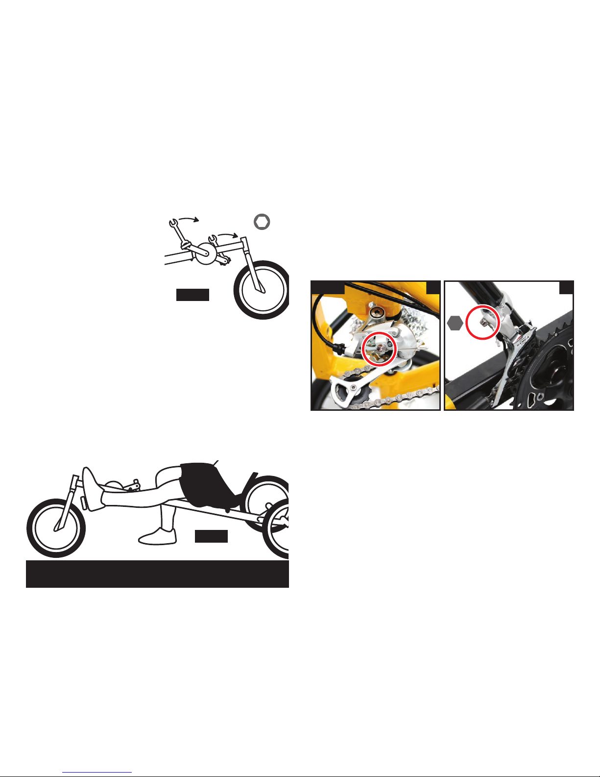
fitting your pedals
Fit the pedals by lightly greasing
the threads and screwing them in.
Fit the shifting plates under the
pedals if desired (schlumpf option
only).
The right hand pedal has a right
hand thread which tightens
clockwise, and the left hand one
has a left hand thread which
tightens anti-clockwise.
to tighten
fig 11
adjusting to your leg length
Sit on the trike to check your leg length. Get comfortable in the
seat and with your leg and the pedal fully extended your heel
should just touch the pedal (fig 12).
If this is NOT the case, loosen the clamping screws on the rear
frame & move the front frame in or out until this is the case.
Make sure to check under the frame’s front section to make sure
that you have not exceeded the max point.
Note: Once you ride the trike you may want to
adjust this position some more until it feels right for you.
fig 12
Please make sure that they are tight.
Your rear derailleur should be in place on the frame so all you
need to do is tighten the cable clasp on the derailleur is tight
with a 5mm Allen Key (fig 13a).
Check the outer casing is sitting properly in the shifter and
derailleur adjuster and the shifter is in the forward position and
pulls the inner cable tight.
Your front derailleur is similar but the cable has been removed.
Put the outer cable into all the stops, move the lever forward and
then clamp the cable in position in the front derailleur (fig 13b).
fig 13 a b
check derailleur cables
If you think you will change the leg length regularly, then you
should consider fitting the trike up with a Chain Gobbler. This
means that you will not need to shorten and lengthen the chain.
5
15
9
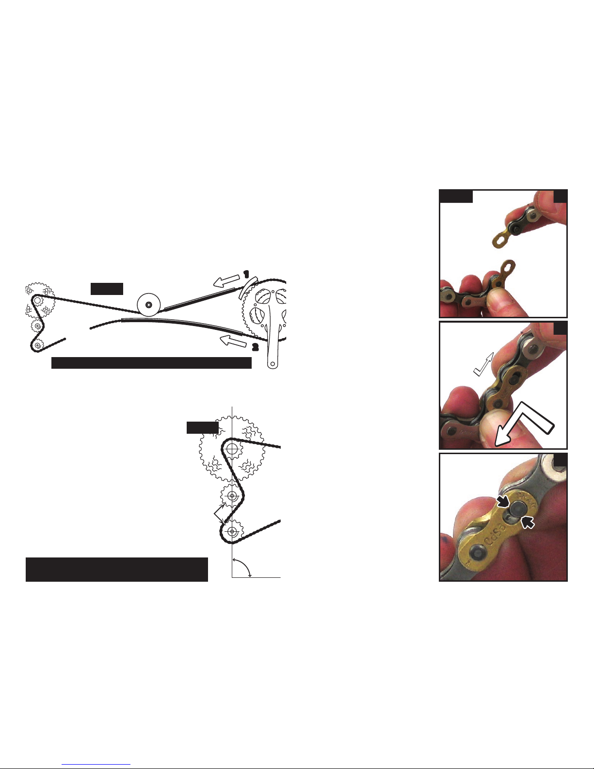
adjusting the chain length
The chain should only be adjusted
once the front frame has been set for
the right leg length. If you have chain
rings, move the chain to the largest
ring on the cranks (no need to do this
for a single ring Schlumpf drive). At
the back, put the chain to the smallest
sprocket (right hand gear shifter all
the way forward) and see if the rear
derailleur cage matches the position
here in (fig 15). Shorten the chain
until the two derailleur cogs are in
alignment. If you do not have a chain
tool, you may need to see your dealer.
fig 15
cogs
90º
Warning: if this chain length is not correct,
damage may occur to your rear derailleur.
Fit your chain next following fig 14. Start by feeding the chain
through the front derailleur cage, down the chain tube, under the
pulley, over the sprockets and down through the rear derailleur
(fig 14, step1).
Put the rest through the lower tube (fig 14, step2).
fitting your chain fig 16 a
b
c
Use the two joining links to
join your chain together.
Slot each link into the chain
ends so that they are opposite
each other (fig 16a) ...
joining your
chain with
split links
When ever you do or undo
the links, always push them
together first so that the
head of the pins go over the
retaining teeth (represented
here in fig 16c by the black
arrows).
Note: Make sure the chain is not twisted inside the tubes.
fig 14
...and slot the pins through
the links (fig 16b) and keep
pushing them towards each
other as you slide them into
position (fig 16b arrows).
10
Then fit the steering rod on to the handle bars (fig 17a) and to
the front forks (fig 17b) with an Allen key screw through the rod
end at each end. The rubber o-ring goes between the rod end
and the front fork to keep the steering silent.
Generally the thicker section with the bend goes to the rear of
the trike with the bend inwards bringing the rod closer to the
trike.
However the steering rod may be fitted either way with the bent
end either bolted to the handle bars, or the front forks. Some
models may need to use the bend at the front end of the trike to
give extra clearance with the cranks. The bend will always face
inwards, bringing the steering rod closer to the frame.
attaching the steering rod
fig 17 a b
aligning your steering
b
90º
Note: be careful not to over tighten the clamp.
If you get the feeling that you steering alignment is changing
whilst riding, check first the leg length scale under the frame
to see if it has moved. More likely you need to tighten your
frame clamp bolts as the frame is sliding together from the
pressure of the chain, rather than the steering.
fig 18 a
Loosen the clamp on the rod
(fig 18a) so that it can slide
telescopically.
Sitting on trike you can then
hold the handle bars so that
they are evenly by your side,
and push the front wheel
with your feet until it is in
alighnment with the frame.
You should end up with
the wheel 90 degree to the
handlebars (fig 18b).
Another technique we are
fond of is to push the front
wheel so that it points hard
right so that steering rod just
touches the frame. Turn your
handle bars hard right until
they hit the stop. With the
front wheel and bars both
hard right, tighten up the
clamp.
Depending on the steering
rod inclination and design this
may not always work, but
if you are changing lengths
regularly, it is great to check
if it will work for you.
5
3
Altri manuali per Anura
1
Indice
Altri manuali Green Speed Bicicletta


