Greenlee CMPL-100-1A Manuale utente

INSTRUCTION MANUAL
999 3283.0 © 1999 Greenlee Textron IM 1419 8/99
CMPL-100-1A
RS-232 INTERFACE ADAPTER
FOR CMPL-100 CLAMP-ON METER
Read and understand all of the instructions
and safety information in this manual before
operating or servicing this tool.

2
Description
The Greenlee CMPL-100-1A RS-232 Interface Adapter is intended to
connect to a PC for data storage and retrieval from the CMPL-100
Clamp-on Meter. It can retrieve stored data and do real-time data
logging and graphing. It also can clear the memory and set the sampling
rate of the meter. Real-time data or retrieved data can be stored to disk
for use in another application.
Safety
Safety is essential in the use and maintenance of Greenlee tools and
equipment. This instruction manual and any markings on the tool
provide information for avoiding hazards and unsafe practices related to
the use of this tool. Observe all of the safety information provided.
Purpose
This instruction manual is intended to familiarize all personnel with
the safe operation and maintenance procedures for the Greenlee
CMPL-100-1A Interface Adapter.
Keep this manual available to all personnel.
Replacement manuals are available upon request at no charge.
and are registered trademarks of
Greenlee Textron.
Windows®is a registered trademark of Microsoft Corporation.
KEEP THIS MANUAL
CMPL-100-1A
3
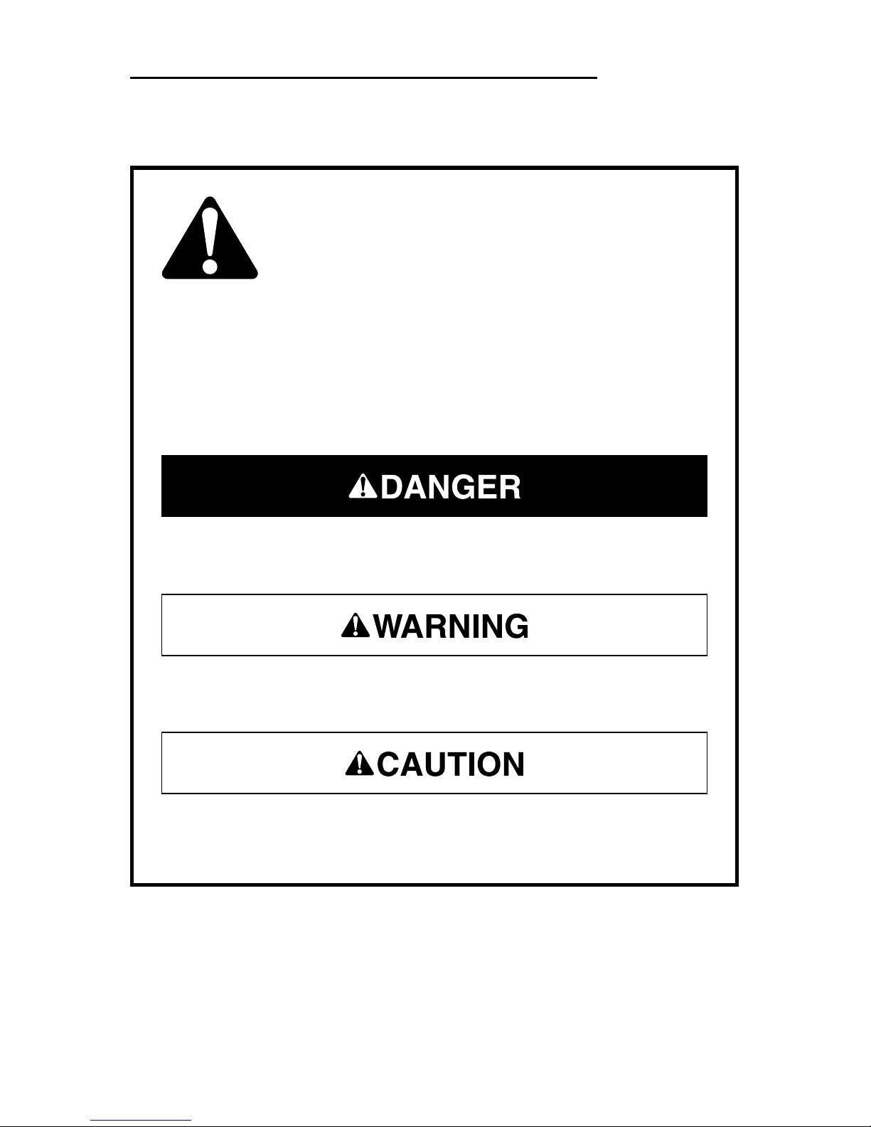
Important Safety Information
This symbol is used to call your attention to hazards or unsafe
practices which could result in an injury or property damage.
The signal word, defined below, indicates the severity of the
hazard. The message after the signal word provides information
for preventing or avoiding the hazard.
SAFETY ALERT SYMBOL
Immediate hazards which, if not avoided, WILL result in severe
injury or death.
Hazards which, if not avoided, COULD result in severe injury or
death.
Hazards or unsafe practices which, if not avoided, MAY result in
injury or property damage.

4
Important Safety Information
Read and understand this material before
operating or servicing this equipment. Failure
to understand how to safely operate this tool
can result in an accident causing serious
injury or death.
Electric shock hazard:
Contact with live circuits can result in severe
injury or death.
Electric shock hazard:
• Do not use the unit if it is wet or damaged.
• Use test leads or accessories that are appropriate for the
application. See the category and voltage rating of the test lead or
accessory.
• Inspect the test leads or accessory before use. The item(s) must
be clean and dry, and the insulation must be in good condition.
Failure to observe these warnings can result in severe injury or
death.

CMPL-100-1A
5
Important Safety Information
• Do not attempt to repair this unit. It contains no user-serviceable
parts.
• Do not expose the unit to extremes in temperature or high
humidity. See Specifications.
Failure to observe these precautions can result in injury and can
damage the unit.
Using this unit near equipment that generates electromagnetic
interference can result in unstable or inaccurate readings.
Electric shock hazard:
• Do not apply more than the rated voltage between any two input
terminals, or between any input terminal and earth ground.
• Do not contact the test lead tips or any uninsulated portion of the
accessory.
• Disconnect leads from circuit before disconnecting adapter unit
from CMPL-100 meter.
• Read and understand instruction manual for the CMPL-100 meter
before using this adapter.
• Do not use with CMPL-100-3A Three-Phase Adapter.
Failure to observe these warnings can result in severe injury or
death.

6
Identification
1. + terminal output to CMPL-100
2. COM terminal output to CMPL-100
3. Optical communication interface
to CMPL-100
4. + terminal input
5. COM terminal input
6. Standard D-shell 9-pin RS-232
communications connector
7. Standard D-shell 9-pin to 25-pin
RS-232 communications adapter
8. Standard 3-1/2 inch floppy disk for
PC compatible computer
Symbols on the Unit
Read the instruction manual.
Double insulation
76
8
2
1
3
5 4
CMPL-100

CMPL-100-1A
7
Hardware and Software Requirements
Minimum Hardware Requirements:
386/25 personal computer
4 Mbytes of memory (RAM)
Windows®3.0
Recommended Hardware:
486/66 personal computer
16 Mbytes of memory (RAM)
Windows®95
NOTES:
•Since this program is compatible with Windows
®
3.0, only 8 letter
filenames and directories are allowed.
•When using the minimum hardware, the fastest PC sampling rate
allowed is 1 second. Also, only one logging function (LIST, CHART, or
SAVE FILE) can be active at a time.
Specifications
Operating and Storage Conditions: 0 °C to 40 °C (32 °F to 104 °F),
0% to 70% relative humidity, non-condensing
Indoor use only
Overvoltage Protection: Category III, 600 Volts

8
Program Installation
Close all other programs before installing the POWER METER software.
Insert floppy disk into drive.
Use RUN function for: A:setup.exe
Install to C:\PWRMETER. Accept this directory, type in one of your
choice, or exit installation.
The necessary files will be copied to the specified destination.
The three files that will be placed in the POWER METER program group
are:
POWER METER This is the main communication program.
GSW.EXE This graphics server is a support program for the
Power Meter. Do not delete this program.
PWRMETER.HLP This is the Windows help file. Do not delete this
program.

CMPL-100-1A
9
Set-Up
1. Turn off the computer.
2. Plug the CMPL-100-1A Interface Adapter into an available serial
port (COM port) on the PC. Use the 9-pin to 25-pin adapter if
necessary.
3. Connect the CMPL-100 to the adapter and turn on the meter.
4. Turn on the computer.
5. Run the program:
START | PROGRAMS | POWER METER | POWER METER
or
START | RUN C:\PWRMETER\Pwrmeter.exe
6. The program should automatically detect which serial communica-
tions port on the PC that the CMPL-100-1A and CMPL-100 meter
are using.
When the CMPL-100 meter is actively communicating to a PC
through the CMPL-100-1A Interface Adapter, the automatic power
off feature is disabled. The typical battery life of the CMPL-100
meter is approximately 10 hours while communicating.

10
Software Display
1. Command Menu
2. Display Box
•Real-time data
•Duplicate of meter’s display
3. PC Data Logging Functions
•Real-time data logging to disk
•Maximum and minimum data
•Set PC sampling rate
4. Data Logger of Meter
•Download CMPL-100 data
•Set time and date of data
•Store data in CMPL-100
•Clear data in CMPL-100
•Set CMPL-100 sampling
rate
5. Refresh Link with CMPL-100
Panel Identification
2
3
4
5
1
Indice
Altri manuali Greenlee Adattatore


