
GREER Company MicroGuard 511 Retrofit Manuale di istruzioni
MicroGuard®511
Retrofit
Rated Capacity Indicator System
Operation


MicroGuard 511 Retrofit i W450512 03/08
Contents
Introduction......................................................................................................................................................................................... 1
System Components............................................................................................................................................................... 1
Extension Sensor ...................................................................................................................................................................... 1
Pressure Transducers........................................................................................................................................................... 1
Anti Two Block (ATB)............................................................................................................................................................... 1
Display............................................................................................................................................................................................ 1
Function Kick-Out ...................................................................................................................................................................... 2
Operator Settable Alarms .................................................................................................................................................... 2
Boom Angle Sensor................................................................................................................................................................. 2
Area Alarm .................................................................................................................................................................................. 2
Operator Console ............................................................................................................................................................................. 3
Crane Configuration ............................................................................................................................................................... 3
Display Console.......................................................................................................................................................................... 4
Operation.............................................................................................................................................................................................. 6
Power Up Self-Test................................................................................................................................................................... 6
Adjusting Brightness & Contrast ..................................................................................................................................... 6
Counterweight............................................................................................................................................................................ 7
Outriggers .................................................................................................................................................................................... 7
Tires and Rigging/Travel...................................................................................................................................................... 7
Stowing the Jib........................................................................................................................................................................... 8
Erecting the Jib ........................................................................................................................................................................ 8
Auxiliary Head............................................................................................................................................................................. 8
Selecting the Winch ................................................................................................................................................................ 8
Setting the Parts of Line ...................................................................................................................................................... 9
Cancel Alarm Button............................................................................................................................................................... 9
Reset Function Kick-Out .................................................................................................................................................... 10
Operator Settable Alarms ................................................................................................................................................ 10
Accessing the Operator Alarms............................................................................................................................. 10
Setting Minimum Boom Angle Alarm................................................................................................................... 10
Setting Maximum Boom Angle Alarm ................................................................................................................ 11
Setting Maximum Boom Length Alarm .............................................................................................................. 11
Setting Maximum Tip Height Alarm...................................................................................................................... 11
Accessing Swing and Work Area Alarms.......................................................................................................... 11
Swing Alarms ......................................................................................................................................................................... 12
Setting the Swing Left and Swing Right Alarms.............................................................................................. 12
Setting the Work Area Alarm.................................................................................................................................. 15

MicroGuard 511 Retrofit ii W450512 03/08

MicroGuard 511 Retrofit 1 W450512 03/08
Introduction
The MicroGuard 511 Retrofit Rated Capacity Indicator System (hereinafter referred to as the
“system”) is intended to aid the crane operator by continuously monitoring the load and warning of
an approach to an overload or two-block condition. Crane functions are monitored by means of high
accuracy sensors. The system continuously compares the load suspended below the boom head with
the crane capacity chart stored in the computer memory. At approach to overload, the system warns
by means of audible and visual alarms. The system can be configured to cause function kickout by
sending a signal to function disconnect solenoids.
System Components
MicroGuard Display Console•
Computer Unit•
Pressure Transducers•
Extension Reel with length and angle sensors•
Anti Two-Block (ATB) switches•
Cables•
Extension Sensor
The extension sensor provides an increasing voltage proportional to the extension of the boom. A
cable attached to the boom head provides a low current electrical path for the ATB signal.
Pressure Transducers
Two pressure transducers measure the pressure in the boom hoist cylinder. The resultant Total
Moment signal is processed to provide a continuous display of the load suspended below the point of
lift.
Anti Two Block (ATB)
A switch monitors the approach of the hookblock or overhaul ball to the boom head. The switch is
held in the normal position until the hookblock or overhaul ball raises a weight that is mounted around
the hoist rope. When the weight is raised, it causes the switch to operate. The resultant signal is
sent to the computer via the extension reel causing the ATB alarm to operate and function kick-out to
occur.
Display
The operator is provided with a continuous display of:
Rated Load•
Actual Load•
Bar Graph showing Percentage of Rated Load•
Radius of the Load•
Boom Angle•
Main Boom Length•
Working Area•
Crane Configuration•
On-screen messages provide the operator with visual warnings of conditions that occur during
operation of the system.

MicroGuard 511 Retrofit 2 W450512 03/08
Function Kick-Out
Electrically operated solenoids disconnect the control lever functions for boom hoist lower, telescope
out, and winch up whenever an overload or an ATB condition occurs.
Operator Settable Alarms
These alarms, when properly set by the operator, define the operating range. This is achieved by
means of minimum and maximum angle, maximum height, and/or maximum length. These alarms
can be programmed for each job site and allow the operator to work in a defined area.
Boom Angle Sensor
Boom angle is measured by means of a high accuracy potentiometer/pendulum assembly that is
damped to prevent over swing. It provides a voltage proportional to boom angle. The boom angle
sensor is mounted inside the cable extension reel assembly.
Area Alarm
When set, this alarm permits the operator to define the operating zone by only two set points. The
use of this method of setting results in a greatly enhanced working area, and also clearly defines the
operating zone.
MicroGuard 511 Retrofit 3 W450512 03/08
Operator Console
Crane Configuration
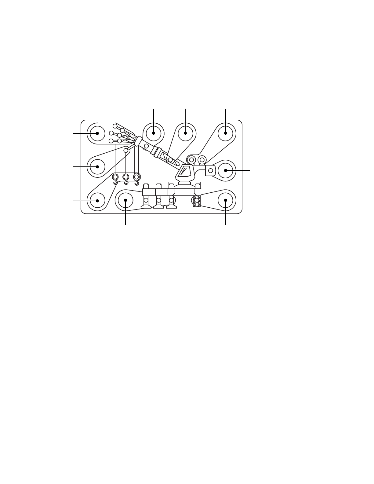
The crane configuration gives a visual representation of the current setup by means of LED
indicators. Each shaded area contains a group of one or more LED and a key that can be pressed
to change the selection. In groups with more than one LED, only one will illuminate to indicate the
selection. The groups are defined below.
2
1
3
4 5 6
87
9
OUTRIGGERS – Indicate full, intermediate, or retracted outriggers.
TIRES – Indicates tires selected.
COUNTERWEIGHT – Active on cranes that have counterweight options.
WINCH – Indicate front or rear winch.
STOWED JIB – This will illuminate when the jib is stowed on the boom.
MANUAL SECTION – Active on cranes that have pinned extensions or active tip boom options.
JIBS – Indicate the length and offset of the jib in use.
AUX HEAD – Illuminates when the auxiliary head is fitted.
POINT OF LIFT – Shows the point of lift.
MicroGuard 511 Retrofit 4 W450512 03/08
Display Console
TEST
SET
MAX
1
5 6 7 8 9 10 11
12
2
3
4
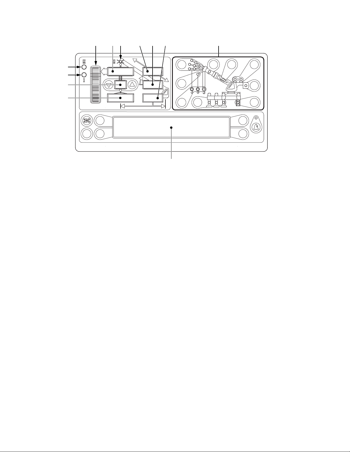
Overload Warning – This red LED illuminates when you reach or exceed 100% of rated1.
capacity. It is accompanied by continuous audible alarm.
Approaching Overload Warning – This amber LED Illuminates when you reach or exceed 90%2.
Rated Capacity. It is accompanied by an intermittent audible alarm.
Parts of Line – Displays current number of parts of line in use.3.
Load on Hook – Displays the entire hook load weight under the head of the boom, including4.
cable, load block, load handling equipment, and weight of load hanging on hook.
Percent of Rated Capacity Meter - Shows the load as a percentage of rated capacity. As the5.
load increases, the meter level increases to represent the percentage of the rated capacity of
the crane.
Rated Capacity – Displays the rated capacity in the current configuration based on the crane6.
load capacity chart.
ATB Warning – Warns of a potential two-block condition with flashing LED and audible alarm.7.
Boom Length – Displays the current boom length in feet and tenths of a foot.8.
Boom Angle – Displays the current boom angle in degrees and tenths of a degree.9.
Load Radius – Displays the load radius from centerline of rotation.10.
Crane Setup – These keys are used in the setup process to configure the system to match11.
the current configuration of the crane.
Information Window – Displays crane setup and calibration information as well as warning12.
messages.
MicroGuard 511 Retrofit 5 W450512 03/08
TEST
SET
MAX
14 15
13
16
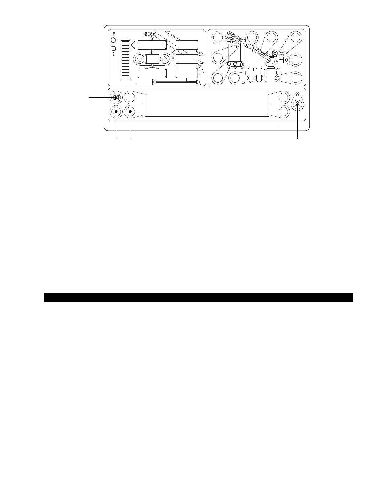
Erected Jib – Enables the selection of the jib to be used on the boom. Selects extended or13.
retracted jib when crane is equipped with two stage jib.
Auxiliary Head - Enables the attachment of the auxiliary head.14.
Outrigger Configuration – Enables the selection between full and mid span outriggers.15.
Stowed Jib – Enables the selection of the jib stowed on the boom. Also used to stow the16.
erected jib.
Winch Selection – Enables the selection of the winch if the crane is equipped with an optional17.
second winch.
Test Button – Press and hold the test button to initiate a system self test and run diagnostics.18.
Alarm Set Button – Enables operator settable alarms. When an alarm has been set, the LED19.
above this button will illuminate yellow.
mWARNING
YOU MUST USE THE CRANE SETUP MODE TO CORRECTLY SET THE SYSTEM FOR PROPER
OPERATION. THE SYSTEM SETUP MUST MATCH THE ACTUAL CONFIGURATION OF THE CRANE
SO THAT IT WILL INDICATE THE CORRECT HOOK LOAD AND LIFTING CAPACITY OF THE CRANE.
MicroGuard 511 Retrofit 6 W450512 03/08
Operation
Power Up Self-Test
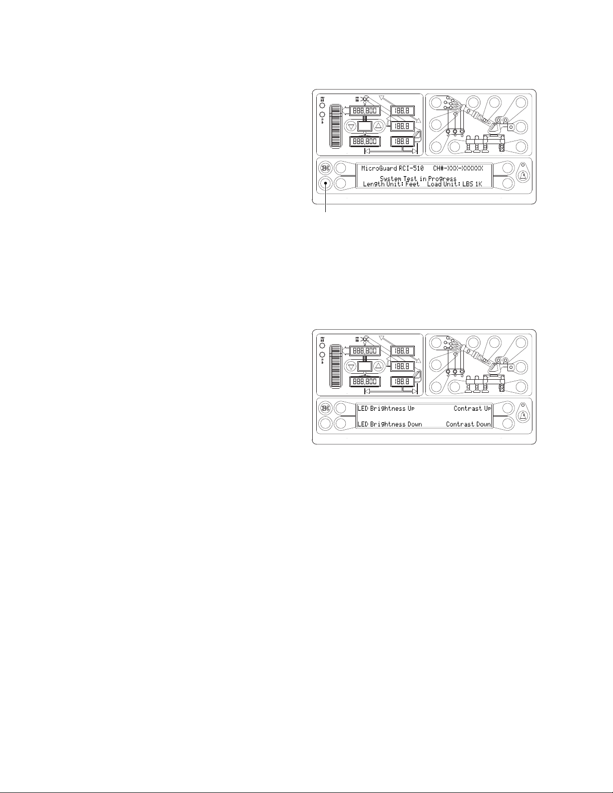
Immediately following electrical power up, or by
manually pressing the TesT key, the system will
execute a self-test lasting for approximately eight
seconds.
During this time, the numerical display segments and
bar graph segments are all turned on, the audible
alarm will sound, and alarm indicator lights and all
other LED’s are illuminated. The information window
will display the crane model, rating chart number, and
units of measure for length and load.
NOTE: At the end of the self-test, the information window will display “CHECK CONFIGURATION
BEFORE YOU CONTINUE”. Press any key to continue, and then verify the setup of the system to the
current configuration of the crane.
Adjusting Brightness & Contrast
Immediately following self-test and the start up
screen, the information window will display the
brightness and contrast control functions for two
seconds.
Press the key adjacent to either “LED Brightness Up”
or “LED Brightness Down” to increase or decrease
the brightness of the LEDs on the display.
Press the key adjacent to either “Contrast Up”
or “Contrast Down” to increase or decrease the
contrast level of the information window.
Brightness and contrast can be adjusted at any time during normal operation except while operator
alarms are being set.
TEST
SET
MAX
TEST
TEST
SET
MAX
Indice
Altri manuali GREER Company Pannello touch

GREER Company
GREER Company MICROGUARD 424 Manuale utente

GREER Company
GREER Company MG-534 Manuale per l'uso e la cura

GREER Company
GREER Company MicroGuard 586 Manuale utente

GREER Company
GREER Company MicroGuard 586 Manuale utente

GREER Company
GREER Company MicroGuard Manuale utente

GREER Company
GREER Company MicroGuard 586 Manuale utente

GREER Company
GREER Company MICROGUARD 424 Manuale utente


