
GSi PNEG-902 Manuale utente
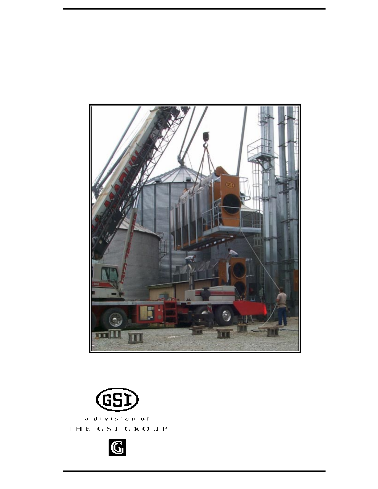
Multi-Module Dryer Stacking
Manual
(Review of Stacking a Dryer)
PNEG-902


3--
Multi - Module Stacking Manual
Contents
Warranty........................................................................................4
Safety Precautions........................................................................5
Stack dryer component callout.....................................................6
Module preparation......................................................................7
Crane bracket placement..............................................................8
Setting lower module on pedestals..............................................9
Anchoring lower module to foundation.....................................10
Installing support legs..................................................................11
Lifting upper module..................................................................12
Setting upper module in place.....................................................13
Securing upper module...............................................................14
Appendix A - Module finishing................................................15
Appendix B - Ladder cage installation......................................16
Notes...........................................................................................18

Multi - Module Stacking Manual
4--
EXCEPT FOR THE ABOVE STATED EXPRESS LIMITED WARRANTIES, GSI MAKES NO WARRANTY OF
ANY KIND, EXPRESSED OR IMPLIED, INCLUDING, WITHOUT LIMITATION, WARRANTIES OF MERCHANT-
ABILITY OR FITNESS FOR A PARTICULAR PURPOSE OR USE IN CONNECTION WITH (i) PRODUCT MANU-
FACTURED OR SOLD BY GSI OR (ii) ANY ADVICE, INSTRUCTION, RECOMMENDATION OR SUGGESTION
PROVIDED BY AN AGENT, REPRESENTATIVE OR EMPLOYEE OF GSI REGARDING OR RELATED TO THE
CONFIGURATION, INSTALLATION, LAYOUT, SUITABILITY FOR A PARTICULAR PURPOSE, OR DESIGN
OF SUCH PRODUCT OR PRODUCTS.
IN NO EVENT SHALL GSI BE LIABLE FOR ANY DIRECT, INDIRECT, INCIDENTAL OR CONSEQUEN-
TIAL DAMAGES, INCLUDING, WITHOUT LIMITATION, LOSS OF ANTICIPATED PROFITS OR BENEFITS.
PURCHASER'S SOLE AND EXCLUSIVE REMEDY SHALL BE LIMITED TO THAT STATED ABOVE, WHICH
SHALL NOT EXCEED THE AMOUNT PAID FOR THE PRODUCT PURCHASED. THIS WARRANTY IS NOT
TRANSFERABLE AND APPLIES ONLY TO THE ORIGINAL PURCHASER. GSI SHALL HAVE NO OBLIGA-
TION OR RESPONSIBILITY FOR ANY REPRESENTATIVE OR WARRANTIES MADE BY OR ON BEHALF OF
ANY DEALER, AGENT OR DISTRIBUTOR OF GSI.
GSI ASSUMES NO RESPONSIBILITY FOR FIELD MODIFICATIONS OR ERECTION DEFECTS WHICH
CREATE STRUCTURAL OR STORAGE QUALITY PROBLEMS. MODIFICATIONS TO THE PRODUCT NOT
SPECIFICALLY COVERED BY THE CONTENTS OF THIS MANUAL WILL NULLIFY ANY PRODUCT WAR-
RANTY THAT MIGHT HAVE BEEN OTHERWISE AVAILABLE.
THE FOREGOING WARRANTY SHALL NOT COVER PRODUCTS OR PARTS WHICH HAVE BEEN DAM-
AGED BY NEGLIGENT USE, MISUSE, ALTERATION OR ACCIDENT. THIS WARRANTY COVERS ONLY PROD-
UCTS MANUFACTURED BY GSI. THIS WARRANTY IS EXCLUSIVE AND IN LIEU OF ALL OTHER WAR-
RANTIES EXPRESS OR IMPLIED. GSI RESERVES THE RIGHT TO MAKE DESIGN OR SPECIFICATION
CHANGES AT ANY TIME.
PRIOR TO INSTALLATION, PURCHASER HAS THE RESPONSIBILITY TO RESEARCH AND COMPLY
WITH ALL FEDERAL, STATE AND LOCAL CODES WHICH MAY APPLY TO THE LOCATION AND INSTAL-
LATION.
THE GSI GROUP, INC. ("GSI") WARRANTS ALL PRODUCTS MANUFACTURED BY GSI TO BE FREE OF
DEFECTS IN MATERIAL AND WORKMANSHIP UNDER NORMAL USAGE AND CONDITIONS FOR A PE-
RIOD OF 12 MONTHS AFTER RETAIL SALE TO THE ORIGINAL END USER OF SUCH PRODUCTS. GSI'S
ONLY OBLIGATION IS, AND PURCHASER'S SOLE REMEDY SHALL BE FOR GSI, TO REPAIR OR REPLACE,
AT GSI'S OPTION AND EXPENSE, PRODUCTS THAT, IN GSI'S SOLE JUDGMENT, CONTAIN A MATERIAL
DEFECT DUE TO MATERIALS OR WORKMANSHIP. ALL DELIVERY AND SHIPMENT CHARGES TO AND
FROM GSI'S FACTORY WILL BE PURCHASER'S RESPONSIBILITY. EXPENSES INCURRED BY OR ON BE-
HALF OF THE PURCHASER WITHOUT PRIOR WRITTEN AUTHORIZATION FROM AN AUTHORIZED EM-
PLOYEE OF GSI SHALL BE THE SOLE RESPONSIBILITY OF THE PURCHASER.
Warranty
5--
Multi - Module Stacking Manual
General Safety Statements
The GSI Group Inc.’s Principal concern is your safety and the safety of others associated with grain handling
equipment. We want to keep you as a customer. This manual is to help you understand safe operating procedures and some
problems which may be encountered by the operator and other personnel.
As owner and/or operator, it is your responsibility to know what requirements, hazards and precautions exist and
inform all personnel associated with, or in the area of the grain dryer. Safety precautions may be required from the person-
nel. Avoid any alteration to the equipment. Such alterations may produce a very dangerous situation, where serious injury
or death may occur.
DANGER indicates an imminently hazardous situation which, if not
avoided, will result in death or serious injury
WARNING indicates a potentially hazardous situation which , if not
avoided, could result in death or serious injury.
DANGER
WARNING
CAUTION used without the safety alert symbol indicates a potentially hazard-
ous situation which, if not avoided, may result in property damage.
CAUTION indicates a potentially hazardous situation which, if not
avoided, may result in minor or moderate injury.
BE ALERT!
Danger!
Personnel operating or working around electrical equipment should read this manual. This manual must
be delivered with equipment to its owner. Failure to read this manual and its safety instructions is a
misuse of the equipment.
CAUTION
CAUTION
This is the safety alert symbol. It is used to alert you to potential personal injury hazards. Obey all safety
messages that follow this symbol to avoid possible injury or death.
This product may have sharp edges! To avoid injury handle sharp edges with caution and use
proper protective clothing and equipment at all times.
If you have any questions regarding installation and safety, please contact your GSI, Inc. repre-
sentative.
Important!
Safety Precautions

Multi - Module Stacking Manual
6--
Stack Dryer Component Callout
Rear Ladders
& Safety Cages
Fill Hopper
Crane Brackets
Pulleys, Belts, & Guards
Wet Bin Assembly
Wiring Connections
Front Ladders,
& Cages
Platform Assembly
Fuel Connections
Control Box Wiring
Stack Dryer
Pedestals & Legs
Module Stiffeners
Lower & Middle Module
Crane Brackets
Module Stiffeners
The following information is intended to help outline the steps required in stacking a Network Dryer.

7--
Multi - Module Stacking Manual
Module Preparation
• Attach the Rear Ladders and Safety Cages to the rear of all modules if not already installed (see
appendix B of this manual).
• Attach the Front Safety Cages to the Front Ladder of all modules (see appendix A of this manual).
See PNEG-1273 for reference.
• Raise the Top Auger to its installed position.
• Install the Wet Bin Side Panels and attach them to the Top Auger Housing.
• Install the Pulleys, Belts, and Guards to the Top Auger and/or to the Bottom Auger.
• Install the Fill Hopper.
See PNEG-349REV for reference.
• Assemble the Service Platform onto the Top Module and/or the Middle Module.
• Attach all of the Stiffener Supports each Module.
• Double check to see if all parts are installed as needed.
Proceed to the Crane Bracket Placement Section >>
• Identify all parts shipped in crates or in the back of the dryer.
• Group parts for each of the assemblies together to have them at hand as needed.
CAUTION
This product may have sharp edges! To avoid injury handle sharp edges with caution and
use proper protective clothing and equipment at all times.

Multi - Module Stacking Manual
8--
Crane Bracket Placement
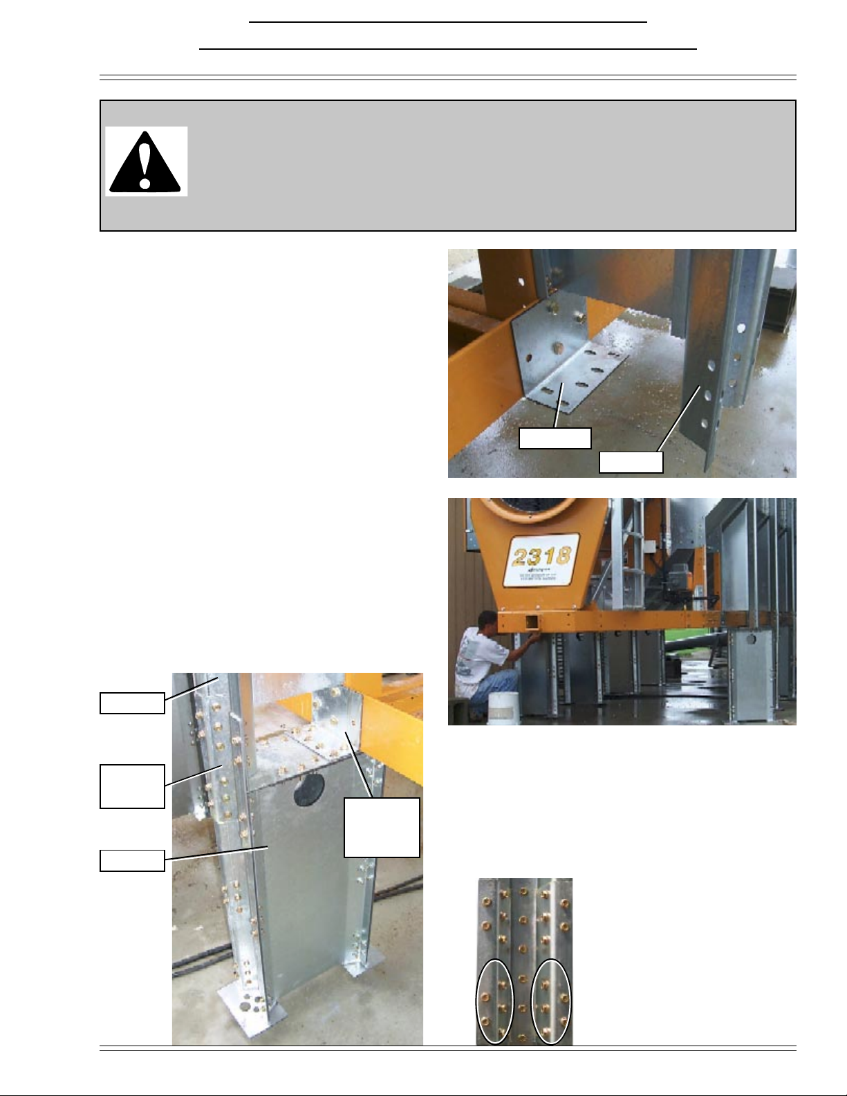
Base Modules and Middle
Modules utilize four crane
brackets. Brackets mount to
stack module support pads.
Lifting usually occurs between
the 2nd column from fan end to
the 6th column from fan end.
This will vary with model
number.
The module should remain
parallel to the earth as it is
lifted. Base Module crane brackets
Top Module crane brackets
Top Modules utilize 2 crane
brackets with 4 lifting points
and a spreader bar between.
These mount to column seams
on the roof screen.
Lifting usually occurs between
the 2nd column from fan end to
the 6th column from fan end.
The module should remain
parallel to the earth as it is
lifted.
Crane Bracket Location
Install the Crane Brackets onto the modules if not already installed.
A crane of sufficient lifting
capability should be used.
Loads of 5,000 to 15,000
pounds should be expected.
Crane Brackets Installed
9--
Multi - Module Stacking Manual
Setting Lower Module on Pedestals
BE ALERT!
Personnel working around this equipment while it is lifted into position must use ex-
treme caution. Lifting equipment (crane and rigging) must be of proper lifting capability
for the unit size and weight. All local safety precautions and procedures must be fol-
lowed.
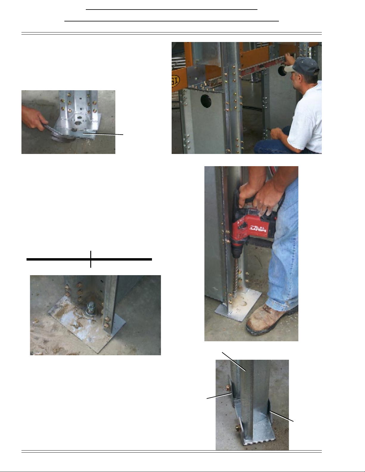
1. Install stiffeners and service platform in accor-
dance with PNEG-349REV. At each stiffener/
pedestal location remove the 1/2” bolts and nuts
that attach the dryer frame leg to the frame rail.
Use that hardware to attach a stiffener base con-
nector clip (D01-1045).
D01-1045
2. Lift base module and position it in the location
the dryer is to occupy. NOTE: Crane brackets
may need to be adjusted to ensure that the
module will be parallel to the ground when
lifted. With the base module in position bolt a
pedestal to each stiffener base connector clip us-
ing 3/8”-16 x 1 1/2” bolts (S-7928).
Stiffener
3. With a stiffener splice (SS-7053), splice the
pedestal to stiffener at each pedestal location. Now
make sure any nuts and bolt used so far have all
been tightened.
Stiffener
Stiffener
splice
Pedestal
When splicing pedestal to
stiffener use 3/8”-16 X 1 1/2”
bolts (S-7928) where circled,
use 3/8”-16 x 1” (S-7927) in all
other holes.
Stiffener
base con-
nector clip
Multi - Module Stacking Manual
10--
4. Set the lower module into final position and
check level. Use shims (SS-6953) to level lower
module if needed.
Shims
Anchoring Lower Module to Foundation
5. Anchor lower module to foundation. If anchor
bolts were not set when the concrete was poured,
then drill holes in the foundation to accept anchor
bolts (use 3/4” x 9 5/8” minimum anchors with
epoxy resin).
GSI has 1” x 12” anchor bolts (Part no. S-8957),
tubes of epoxy (GTC-0004), and mixing nozzles
for epoxy tubes (GTC-0005). An epoxy gun will
be needed.
6. Attach front (BLK-10058) and back (BLK-
10057) leg anchor plates to legs using 5/16”-18 x
3/4” bolts (S-6606), and 5/16”-18 nuts (S-3611)
as shown in the photo on the right. BLK-10057
BLK-10058
LEG STAND
Basket length 14' 18' 20' 22' 26'
No. of anchors needed 16 20 22 24 28
Altri manuali per PNEG-902
1
Indice
Altri manuali GSi Asciugatrice

GSi
GSi 1100 Manuale utente

GSi
GSi 2314 Manuale utente

GSi
GSi PNEG-2132 Manuale utente

GSi
GSi CSA - Mod/T Manuale utente

GSi
GSi TM-Series Manuale utente

GSi
GSi PNEG-902 Manuale utente

GSi
GSi Domestic - Mod/T Manuale utente

GSi
GSi 1100 Manuale utente

GSi
GSi TopDry Autoflow 2000 Series Manuale utente

GSi
GSi 1100 Manuale utente


