
GW Instek GDM-SC1 Manuale utente

Scanner Card
GDM-SC1
INSTALLATION GUIDE
GW INSTEK PART NO. 82DM-SC100ED1
ISO-9001 CERTIFIED MANUFACTURER

December 2013
This manual contains proprietary information, which is protected by
copyrights. All rights are reserved. No part of this manual may be
photocopied, reproduced or translated to another language without
prior written consent of Good Will company.
The information in this manual was correct at the time of printing.
However, Good Will continues to improve products and reserves
the right to change specifications, equipment, and maintenance
procedures at any time without notice.
Good Will Instrument Co., Ltd.
No. 7-1, Jhongsing Rd., Tucheng Dist., New Taipei City, 236, Taiwan.
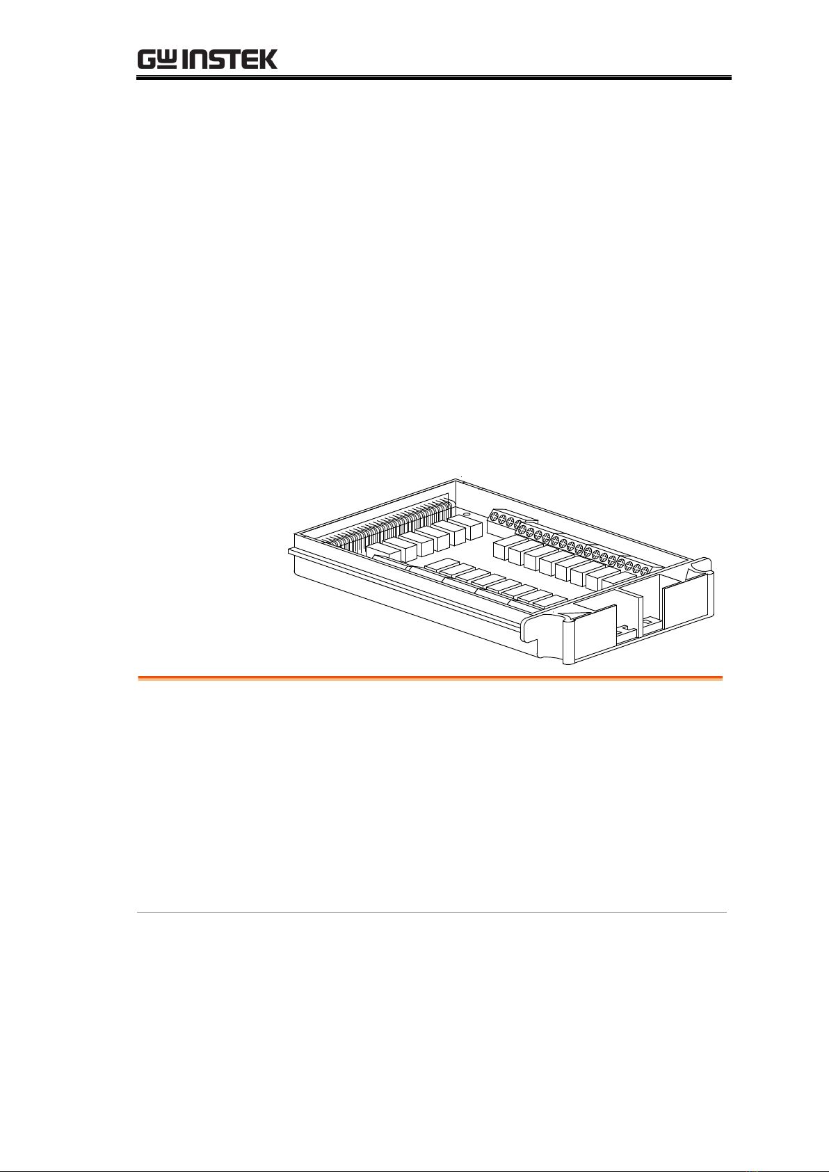
GDM-SC1 Scanner Card
SCANNER CARD
The optional scanner, GDM-SC1, lets you effectively
measure multiple channels when connected to a
GDM-8255A, GDM-8261 or GDM-8261A multimeter.
Up to two GDM-SC1 scanner cards can be installed into
the GDM-8255A or one GDM-SC1 into the GDM-8261
or GDM-8261A. If two scanner cards are installed, one
can be selected as the master scanner (channel 1), and the
other as the slave (channel 2).
Installation
GDM-SC1 Basic Specifications.................................4
Configure scanner ....................................................4
Select Channel group and enable scanner................6
Connect wire ............................................................7
Insert scanner ........................................................10
Scanner Configuration Record................................12
Specifications
Specifications .........................................................13

GDM-SC1 Basic Specifications
GDM-SC1 Basic Specifications
2-wire channel
16 pairs
Maximum current
2A (ch17, ch18)
4-wire channel
8 pairs
Resistance
2/4 wire
Single wire channel
N/A
Cold junction
N/A (internal)
Maximum voltage
250V
Connection
Screw terminal
Scanner Installation
Configure scanner
Open Scanner
cover
1. Take off four screws from the bottom panel of the
scanner.
2. Remove the top panel.

GDM-SC1 Scanner Card
3. Note the connection terminals.
Overview
16 general purpose channels are available, 8 on the left
row, 8 on the right row. Current (ACI, DCI) measurement
uses 2 extra channels. All channels are fully isolated (Hi
and Lo).
Scan/Step
connection
Refer to the below table for measurement and test line
connection.
Note: Not all items can be used with the GDM-8255A.
Item
No. of wires
No. of channels
DCV, ACV
2 wires (H, L)
16 (CH1 ~ 16)
DCI, ACI
2 wires (H, L)
2 (CH17, 18)
(10A range only)
2W Resistance
2 wires (H, L)
16 (CH1 ~ 16)
4W Resistance
4 wires (Input H,
L + Sense H, L)
8 pairs (CH1
[input]& 9[sense],
2&10,....8&16)
Diode/Continuity
2 wires (H, L)
16 (CH1 ~ 16)
Period/Frequency
2 wires (H, L)
16 (CH1 ~ 16)
Temp.
(Thermocouple)
2 wires (H, L)
16 (CH1 ~ 16)

Scanner Installation
Temp. 2W RTD
2 wires (H, L)
16 (CH1 ~ 16)
Temp. 4W RTD
4 wires (Input H,
L + Sense H, L)
8 pairs (CH1
[input]& 9[sense],
2&10,....8&16)
Select Channel group and enable scanner
Background
When 2 scanner modules are installed in the
GDM-8255A, 2 groups of 18 channels each are available.
The scanner modules have a jumper to configure which
scanner is for which group. If only one scanner is
installed, the scanner should always be configured to
group 1(CH101~CH118).
The GDM-8255A can have up to 2 scanner modules
installed, whilst the GDM-8261/GDM-8261A can have
only 1 scanner module installed.
Group1
CH101 ~ 118
Group2
CH201 ~ 218
Select group
(Jumper J8)
Set the jumper J8 in the center of the board accordingly.
Move the jumper to the right (pins 2-3) for selecting
CH1xx (101 ~ 118), and move to the left (pins 1-2) for
selecting CH2xx (201 ~ 218). If two scanners are
installed, set one scanner to Master (CH1xx) and the
other to Slave. If only one scanner is installed, set the
jumper to Master.
1 2 3
J8
1
2
3
1
2
3
CH201-218
SLAVE
CH101-118
MASTER
J8

GDM-SC1 Scanner Card
Enable scanner
(Jumper J9)
Set the jumper J9 on the rear side of the board
accordingly. Move the jumper up (pins 3-2) to disable the
scanner, and down (pins 2-1) to enable the scanner.
3
2
1J9
3
2
1
3
2
1
Enabled
Disabled
J9
Connect wire
Wire selection
Make sure the wires have at least the same Voltage and
Current capacity as the maximum ratings in the
measurement.
Connection
1. Turn the screw left (loose) using the screw driver and
insert the wire. Turn the screw right (tight) and
secure the connection.
Tighten
Loosen Insert

Scanner Installation
2. Route the wires as follows, using the two openings
(left and right) at the front cover.
Note
When using thermocouple wiring, please use
extension wires so that the cold junction points are
external to the scanner card. Connecting
thermocouple wiring directly to the scanner box is
not recommended due to the radiant heat from the
internal components.
Best if longer
than 20cm Thermocouple
wire
Cold junction
points
Extension
wires Hot junction
point
3. Bundle the wires at the front cover using the holes at
the bottom.

Scanner Installation
Insert scanner
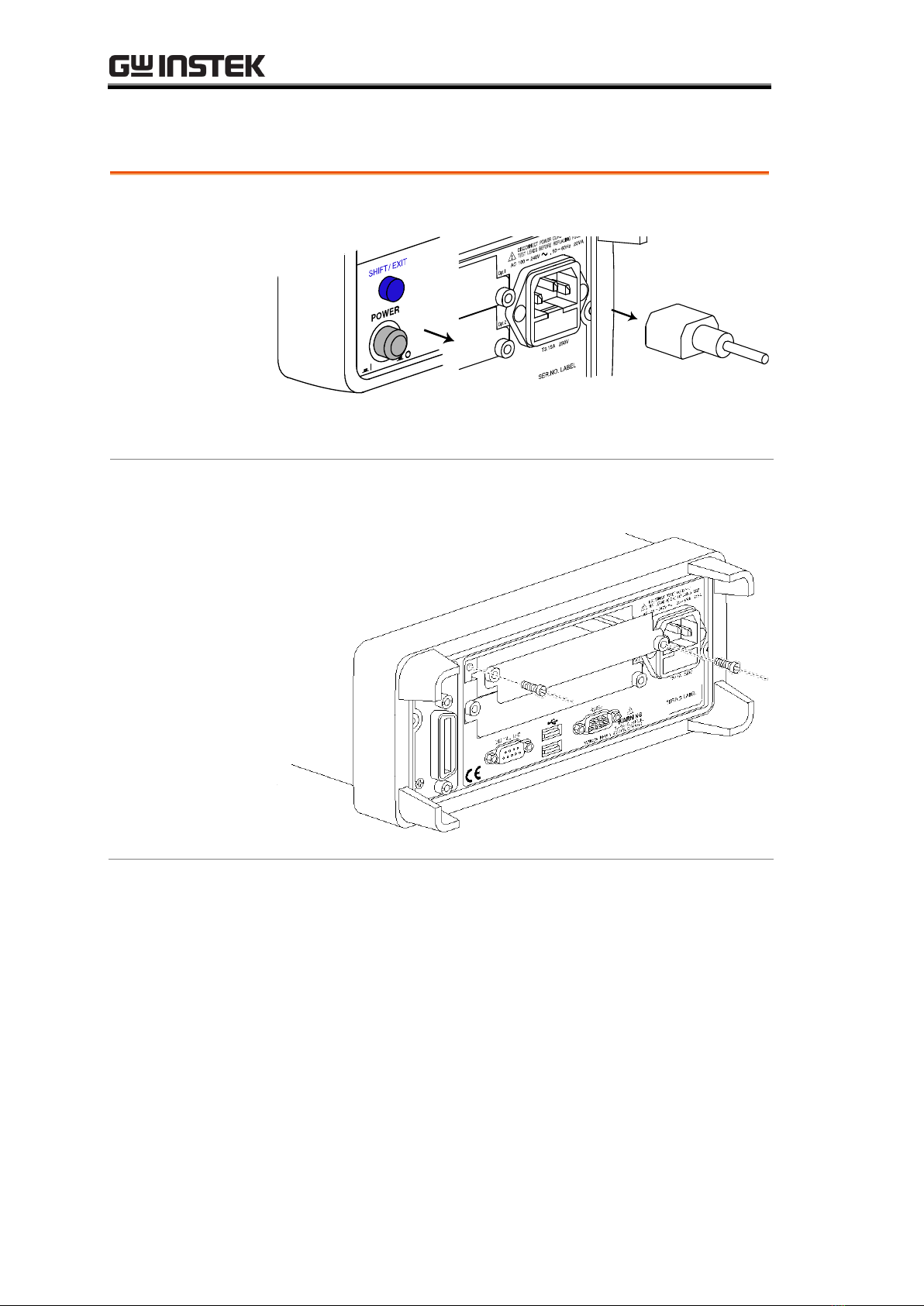
Power Off
Turn the Power Off and take out the power cord.
Open the rear
panel slot
Take out the two screws on the slot corners to remove the
optional slot cover. Keep the screws for later reuse.
GDM-8255A shown
Indice


