
Ham radio HF2013DX-A Manuale utente

HF2013DX-A
HF POWER AMPLIFER
CAUTION
Before you turn the amplifier on, at least 2 hours should have expired since
it was brought in and unpacked in the room where it will be used. Pay
particular attention when you move it from a very cold into a very warm place
- condensation is likely and this could result in damage to the high voltage
circuits. In such a case, wait at least hours. A similar effect can occur after
a rapid warming of the operating room (for instance after switching on a
powerful heater).
CAUTION
To avoid

HF2013DX-A HF AMPLIFER INSTRUCTION MANUAL
Page 2 of 37
Instruction Manual
Version 1 09

HF2013DX-A HF AMPLIFER INSTRUCTION MANUAL
Page 3 of 37
IMPORTANT SAFETY INSTRUCTIONS:
WARNING - GROUNDING
Have i mi d that the grou di g system may have to withsta d curre ts over 20A with
i sig ifica t voltage drop o it. Thereforeit may be ecessary for your to improve it co siderably.
The grou di g leads should be at least 8mm2(AWG 8 or SWG 10) or braid size of ¾ to 1 i ch
CAUTION
If this is the first time you have used a high power amplifier i your statio , pay atte tio to the
coaxial cable type from the amplifier output. It must ha dle the i creased power safely –
particularly o the higher freque cy ba ds. We recomme d you use RG213, LMR400 or better
coaxial cable. Similar good quality coaxial cable should be used throughout your a te a
system. Check the power capability of the a te a selector, the matcher, a d the a te a itself
(especially multiba d trap a te as)
WARNING HIGH VOLTAGE
This amplifier works with very high voltages up to 3300V, which is LETHAL! For your safety
remove the power plugs a d WAIT AT LEAST 30 mi utes EACH TIME BEFORE you remove the
cover of the amplifier. Do ot touch a y part i side while the amplifier is ope as some residual
voltages may still be prese t.
WARNING HIGH VOLTAGE
Never allow a yo e, ESPECIALLY CHILDREN, to push a ythi g i to the holes i the case – this
will cause electric shock. NEVER TOUCH AN ANTENNA duri g tra smissio – this may result
i a electric shock or bur . NEVER EXPOSE the amplifier to rai , s ow, or a y liquids. AVOID
placi g the amplifier i excessively dusty e viro me ts or i direct su light..
WARNING
DO NOT OBSTRUCT AIRE INTAKE (real pa el) a d EXHAUST (top cover, left rear) areas of the
amplifier. Keep a mi imum dista ce of 10cm (4 i ches) to the i take a d 50cm (20 i ches) to the
exhaust Do ot u dertake repairs, cha ges to hardware or software of the amplifier i order ot
to e da ger your or others health a d life a d ot to damage the amplifier a d the equipme t
co ected with it. A y such repair, cha ge or modificatio will void the warra ty. The
ma ufacture is ot liable for theactio of a other a d respo sibility shall be assumed by the
ow er.
This amplifier co tai s very high voltage circuits. Never tur the amplifier o without
the upper lid i place.This high voltage is lethal!!!
TheHF2013DX-A amplifier must ot be used i a wet or humid e viro me t or to be
exposed to rai fall.
The amplifier must be i stalled so that free flow hot air from the tube is u restricted.
Do ot i stall the amplifier i a area that could co strai airflow.

HF2013DX-A HF AMPLIFER INSTRUCTION MANUAL
Page 4 of 37
Duri g lo g operatio the upper lid a d the ve t grid of the amplifier ca reach high
temperatures that ca cause bur i juries. Do ot touch these parts of the amplifier
duri g operatio .
The amplifier must be grou ded to your statio earth.
The amplifier must be i stalled to e sure u restricted access to the rear power
co ectors.
The amplifier will o ly operate if both 2kw power cables are co ected. I sure that
you have two i depe de t 2kw a/c supplies that are capable of supplyi g 10 Amps
each with a maximum worki g curre t of 18 Amps a/c
Do ot tur the amplifier o without havi g co ected the a te a first. There is
pote tial for a hazardous HF voltage build-up.
Before ope i g the upper lid of the amplifier make sure that both power supplies have
bee disco ected for at least 10 mi utes allowi g the electrolytic capacitors to
discharge fully. Never tur the amplifier o withoutthe upper lid i place.
Make sure that all screws holdi g the case together are properly i place a d tied
before carryi g the amplifier by the ha dles.
This amplifier is a A category product. I a household it ca i terfere with other
electrical applia ces. I such cases the user is to take proper actio s to mitigate this
disturba ce, by usi g proper statio earth, use of Ferrite beads, high quality a te as
a d high quality coax such as LMR400 or better.

HF2013DX-A HF AMPLIFER INSTRUCTION MANUAL
Page 5 of 37
Table of Contents
GENERAL DESCRIPTION OF THE HF2013DX-A AMPLIFIER 6
SPECIFICATION OF HF2013DX-A 6
DESCRIPTION OF HF2013DX-A POWER AMPLIFIER 8
PUTTING THE POWER AMPLIFIER INTO OPERATION 12
COOLING 15
OPERATION 16
CONFIGURING AND OPERATING THE HF2013DX-A POWER AMPLIFIER 17
TUNING 24
TUNING INSTRUCTIONS 25
INDICATION OF FAULT CONDITIONS 28

HF2013DX-A HF AMPLIFER INSTRUCTION MANUAL
Page 6 of 37
GENERAL DESCRIPTION OF THE HF2013DX-A A PLIFIER
The li ear amplifierHF2013DX-A is desig ed for all short wave amateur ba ds from 1.8MHzto
29MHz (i cludi g WARC – ba ds) a d all operati g modes. It is equipped with a ceramic
tetrodeFU728F(4CX1500B). The HF2013DX-Ais automatically tu ed to the operati g
freque cy of your TRX whe the correct co trol cable is co ected.
SPECIFICATION OF HF2013DX-A
Freque cy coverage: Amateur ba ds1.8Mhz – 29.7 MHz i cludi g WARC
Power output: 2000 W PEP i SSB a d CW 1800W i RTTY,
AM a d FM
Drive Power: usually 60 to 73 W for full Output Power
I put impeda ce: 50 Ohm VSWR <1.5 : 1
Output amplificatio : 17 dB
Output impeda ce: 50 Ohm u bala ced
Maximum output SWR: 2:1
SWR protectio : automatic switchi g toSTBY, whe reflected power is
350W or higher
I termodulatio distortio : 32 dB below omi al output
Suppressio of harmo ics: < -50 dBc
Tu i g Ma ual or Auto
Respo se speed of AUTO less tha 0.5s withi same BAND
Less tha 3s if out of BAND
Supported TRXs-CAT ICOM, ELECRAFT, KENWOOD, TEN-TEC,
YEASU a d ICOM tra sceiver protocol used by
microHAM devices – CI-V OUPUT
Tube: FU728F Ceramic tetrode (similar to a 4CX1500B)
Cooler: EBM Ce trifugal blower + axial blower
Power supply: 2 x 230 VAC2kw, 50 Hz o e or two phases
Tra sformers: 2 x toroidal tra sformer 2.0 kVA
Protectio circuits: - SWR too high
- a ode curre t too high
- scree curre t too high
- grid curre t too high
- Mistu i g of power amplifier
- Hot switchi g protectio
- Soft start for protecti g your fuses
- Switch–o blocki g whe top cover is ope ed.

HF2013DX-A HF AMPLIFER INSTRUCTION MANUAL
Page 7 of 37
5 INCH LCD COLOUR DISPLAYINDICATORS :
WAIT - preheati g of tube (150 sec)
WAIT - preheati g of tube completed.
STBY - sta dby
OPR - operati g co ditio
FAULT - failure,Will switch to STBY for 2 seco ds a d back
to operate.
FPW - Forward power output
SWR - Sta di g Wave Ratio
RPW - Reflected Power
TUNE - Tu e scale i dicator
BUTTONS ∧
∧∧
∧/∨
∨∨
∨ Lists items i me u
MAN Ma ual Operatio mode – See tu i g sectio
AUTO Automatic operati g mode, setti gs recalled from
Memory.
TUNE Tu i g
SET Co firmatio of selected item i me u.
ON/OFF Mai s Power o / off
OPR/STBY Operate a d Sta dby modes.
OSD INDICATION LCD display 2x32 Characters
Colour 5 i ch LCD I formatio Pa el
DIMENSIONS: 485 x 200 x 455mm (width x height x depth)
WEIGHT: 38 kg
HF2013DX-A HF AMPLIFER INSTRUCTION MANUAL
Page 8 of 37
DESCRIPTION of HF2013DX-A POWER A PLIFIER
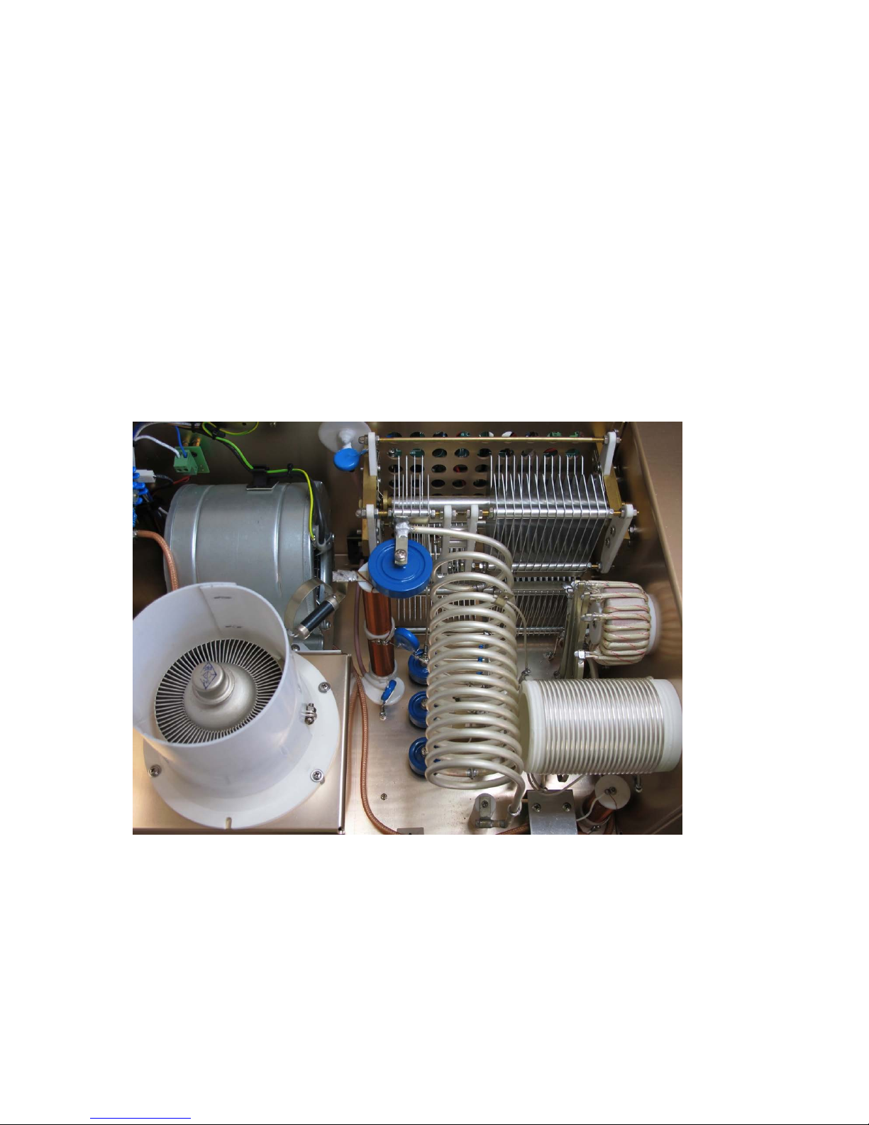
I this amplifier a tetrodetubeFU728F (similar to a 4CX1500B)is used i a grou ded-cathode
circuit (i put i to co trol grid). This amplifier achieves excelle t li earity by the voltage
stabilizatio of the co trol grid bias a d the scree voltage. The power i put is give to the
co trol grid, usi g a broadba d i put circuit with a i put impeda ce of 50 Ohms. This
adaptable i put circuitry e sures a good i put SWR better tha 1.5:1 o all short-wave ba ds.
The output of the amplifier is a Pi-L circuit. The ceramic capacitor for TUNE a d LOAD are
divided. This e ables the amplifier to be tu ed exactly a d makes it possible to easily retur
to the previously set positio s after ba d cha ge.
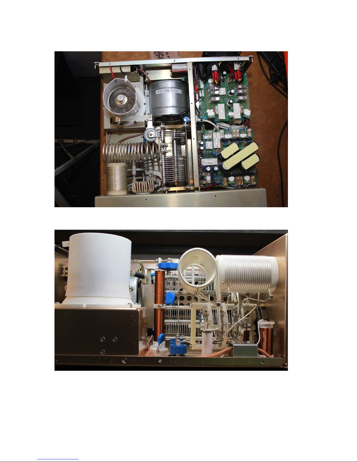
TOP VIEW OF OPENEDHF2013DX-A
HF2013DX-A HF AMPLIFER INSTRUCTION MANUAL
Page 9 of 37
TOP VIEW OF OPENED HF2013DX-A
SIDE VIEW OF OPENED HF2013DX-A

HF2013DX-A HF AMPLIFER INSTRUCTION MANUAL
Page 10 of 37
POWER SUPPLY BOARD OF THE HF2013DX-A
SWITCH ON BOARD OF THE HF2013DX-A
Indice


