HBX ORC-0100 Manuale utente

HBX Control Systems Inc.
Installation Manual
ORC-0100
Version 1.02
ORC-0100

© 2018 HBX Controls2
INTRODUCTION
This manual will help with the installation, parameter setting, troubleshooting
and general maintenance requirements for the Controller. To guarantee the
safe and reliable operation of this Control, you must rst read this manual in
detail and take particular note to any and all warnings or caution directives
prior to connecting to AC power.
Only suitably qualied individuals with formal training in electrical and HVAC
controls should attempt the installation of this equipment. Incorrect wiring
and installation will affect the warranty provided with this unit. Wiring must be
completed in accordance with the codes and practices applicable to the
jurisdiction for the actual installation.
SAFETY SYMBOLS AND WARNINGS
Drawing reference
Refer to the specied electrical drawing at the back of the manual.
Precaution
A measure taken in advance to prevent dangerous or an
unpleasant event
TABLE OF CONTENTS
Introduction Index
Safety Symbols and Warnings Index
Receipt and Inspection 1
Description 1
Technical Data and Dimensions 1
Programming ORC-0100 2 - 3
- Navigating the ORC-0100 2
- Boiler Adjustments 2-3
Connection and Wiring 4-7
Connections 4
Wiring Diagrams 4-7
Limited Warranty 9
Index
WARNING: This product can expose you to chemicals including lead, which
is known to the State of California to cause cancer and birth defects or other
reproductive harm. For more information go to www.P65Warnings.ca.gov.
!

1
RECEIPT & INSPECTION
After receiving, inspect the unit for any possible physical damage that may
have occurred during transportation. After unpacking the unit make sure the
box contains:
• 1 x Universal sensor
• 1 x Outdoor reset control ORC-0100
• 1 x Outdoor Sensor
• 1 x Screwdriver
• Instruction Manual
• 1x Tie Wrap
DESCRIPTION
The HBX ORC-0100 is designed to be an energy-saving automatic control for
hot water boilers. The ORC-0100 measures the outside air temperature and
re-adjust the heating system water to a minimum water temperature to satisfy
the heat loss of the home or building.
Some features of the ORC-0100 are:
• Backlit graphic display
• Push button keypad control
• User-friendly programming features
• Includes external sensor
• Integrated 2 Amp dry contacts
Technical Data
3 x Contact Output
(120VAC 2 Amp Max)
2 x External Thermistor Input
1 x Power Contact: 24VAC
Dimensions: 115 x 80 x 27.5mm
ETL Listings:
Meets CSA C22.2 No. 24
Meets UL Standard 873
ETL Control No. 3068143
Storage: +10C to +40C
Languages: English
115mm
(4.53in) (1.08in)
(3.15in)
80mm
27.5mm
TECHNICAL DATA AND DIMENSIONS
© 2018 HBX Controls2
PROGRAMMING ORC-0100
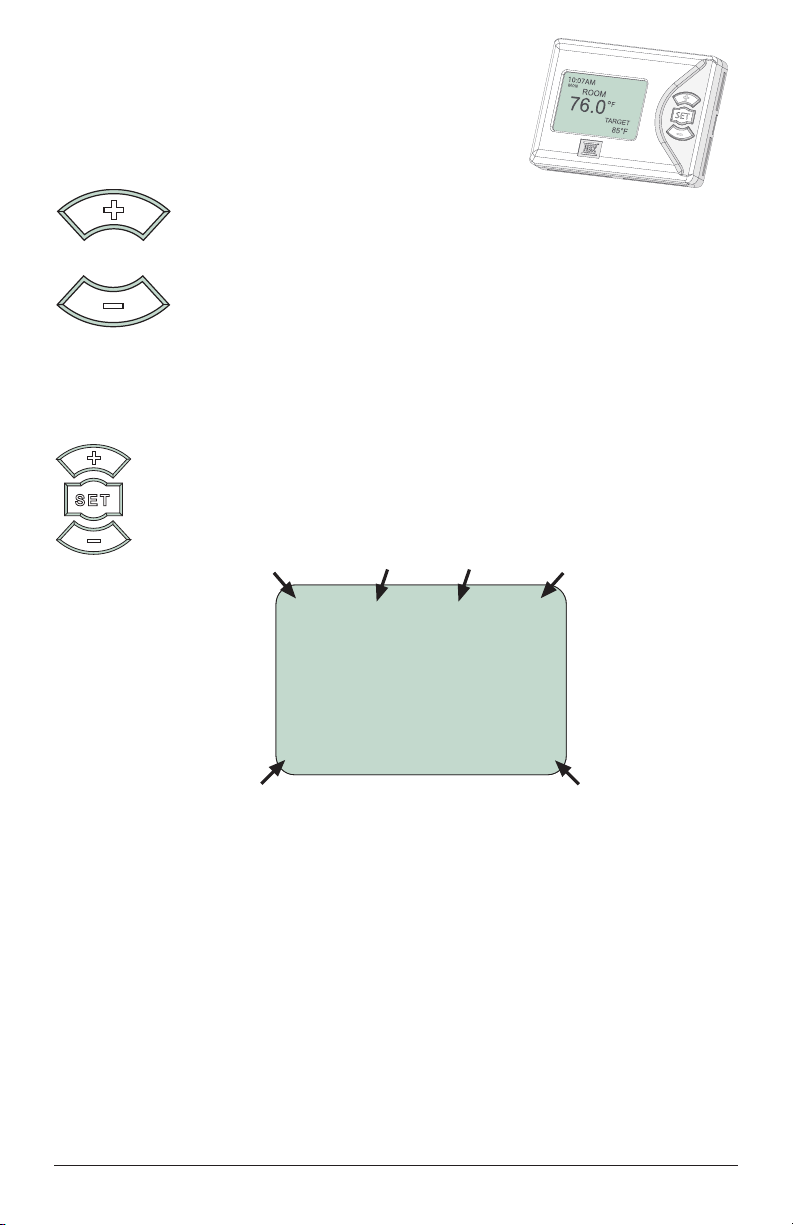
navigating the outDoor reset control
All programming steps within the outdoor reset
control are achieved by using the three buttons
(and combinations thereof) located on the right-
hand side of the thermostat.
The + button is used to scroll up in
menu screens and increase a value
within specic options.
The - button is used to scroll down in menu screens and decrease
a value within specic options.
Boiler aDjustment screen
Holding down the set button for 2 seconds while viewing the “Status Screen” will
take you into the “Adjustment Screen”.
Once you are in the desired options screen, use the +and -button to
scroll up and down. Press down the set button to choose the option
(the arrow to the left of your chosen option will turn black when you
have selected a specic step), then the +and -buttons to adjust the
value.
sPecial features
1) System pump pre-purge (30 seconds)
This will allow any residual heat to be taken out of the boiler before ring
the boiler. This feature is designed to reduce short cycling.
2) System Pump Post Purge (60 seconds)
After the heat demand has been satised, the system pump will stay on for
60 seconds. This will reduce a spike in temperature in the boiler when the
demand goes away.
3) DHW Priority (60 minutes)
This allows the user to select whether they would like the main system pump
to go off if there is a DHW demand. If priority is yes when there is a DHW call
and WWSD is on, the system pump will not come on.
78.7°F
HD ON
Boiler Status
Domestic
Hot Water
Warm Weather
Shut Down
DHWWWSD
Heat
Demand
BOILER
OUTDOOR
-1°F TARGET
190°F
Outdoor
Temperature
Target
Temperature

3
Maximum Boiler Temperature
“Maximum Boiler Temperature” is used in the
outdoor reset design calculation, and also serves as
the maximum setting for the boiler.
BOILER ADJUSTMENTS
1) MAX BOILER 190°F
2) MIN BOILER 120°F
3) OUT DESIGN -10°F
4) DIFF 6°F
5) WWSD 72°F
Minimum Boiler Temperature
Reduces the risk of condensing ue gases. It can run
with both condensing, and non-condensing boilers.
Setup as per boiler manufacturers recommendation.
BOILER ADJUSTMENTS
1) MAX BOILER 190°F
2) MIN BOILER 120°F
3) OUT DESIGN -10°F
4) DIFF 6°F
5) WWSD 72°F
Outdoor Design Temperature
The “Outdoor Design Temperature” option should
be set to reect your specic city or region. It factors
into the outdoor reset curve calculation.
BOILER ADJUSTMENTS
1) MAX BOILER 190°F
2) MIN BOILER 120°F
3) OUT DESIGN -10°F
4) DIFF 6°F
5) WWSD 72°F
Differential
A differential of 10° is 5° above setpoint and 5°
below setpoint. Range from 2°F to 60°F.
BOILER ADJUSTMENTS
1) MAX BOILER 190°F
2) MIN BOILER 120°F
3) OUT DESIGN -10°F
4) DIFF 6°F
5) WWSD 72°F
Warm Weather Shutdown
“Warm Weather Shutdown” is the outdoor
temperature that must be reached for the control to
enter an energy-saving hibernation mode.
BOILER ADJUSTMENTS
1) MAX BOILER 190°F
2) MIN BOILER 120°F
3) OUT DESIGN -10°F
4) DIFF 6°F
5) WWSD 72°F
Domestic Hot Water Priority
This option will allow the DHW demand to override
the heating system for a max of 60mins in order
to satisfy the DHW demand. Once the control
switches to DHW priority, the DHW target will be the
Maximum Boiler Temperature. If after the 60mins
there is still an unsatised heat demand, the ORC-
0100 will automatically switch the system pump
back on to accommodate the call for heat. Once
the control switches to heat mode, the heat target
will be calculated based on the actual outside
temperature.
BOILER ADJUSTMENTS
1) MAX BOILER 190°F
2) MIN BOILER 120°F
3) OUT DESIGN -10°F
4) DIFF 10°F
5) WWSD 72°F
6) DHW PRTY OFF
Refer to diagram #4 Outdoor Reset Curve
Refer to diagram #4 Outdoor Reset Curve

© 2018 HBX Controls4
CONNECTIONS AND WIRING DIAGRAMS
connections
wiring Diagrams
#1. Permanent heat DemanD
Transformer
R C
24VAC
Pump contact is dry
120VAC 2A max
rating. Larger loads
must use an external
relay
L
N
120 V AC
Jumper
Wire
Pump
Enable
Pump enable has a 30
second pre-purge and
60 second post-purge
Boiler
Enable
Outdoor
Sensor
Boiler
Sensor
THM-0200
HBX
RL
2
RL
32
22
24V AC
109
2
TH
2
TH
87
3
Thermostat
RL
1
RL
54
1
2 A
DO NOT
CONNECT
POWER HERE
TH
1
6
RL
1
2 A
1
ORC-0100
5
BOIL
SEN
OUT
SEN
24 V AC
Boiler
Enable
Thermostat
Transformer
ORC-0100
HBX
RL
2
RL
32
22
24V AC
109
2
TH
2
TH
87
3
Thermostat
RL
1
RL
54
1
2 A
DO NOT
CONNECT
POWER HERE
TH
1
6
RL
1
2 A
1
L
N
120 V AC
A
8
4
1
5
9
12
14
13
DHW
PUMP
BOILER
PUMP
TH
AquaStat
C
R
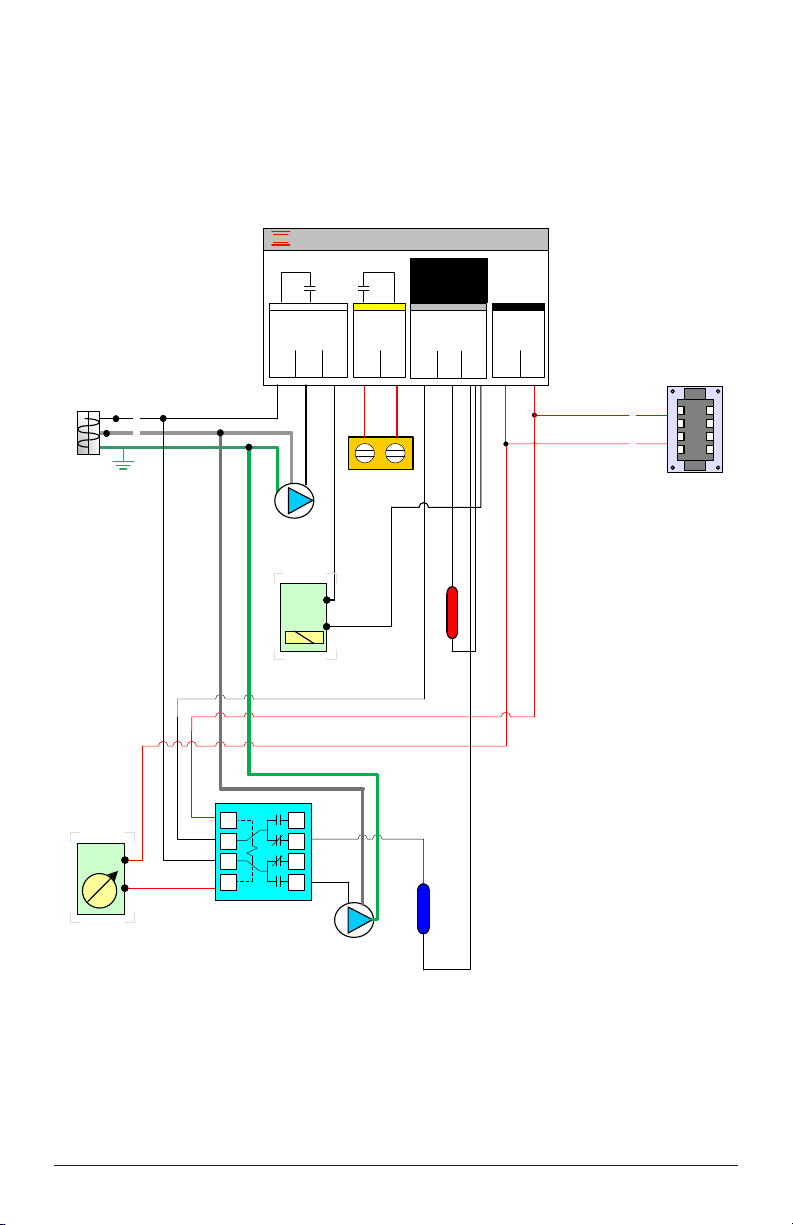
#2. Domestic hot water

© 2018 HBX Controls6
#3. external thermostat
Transformer
R C
24VAC
TH
Thermostat
Pump contact is dry
120VAC 2A max
rating. Larger loads
must use an external
relay
THM-0200
HBX
RL
2
RL
32
22
24V AC
109
2
TH
2
TH
87
3
Thermostat
RL
1
RL
54
1
2 A DO NOT
CONNECT
POWER HERE
TH
1
6
RL
1
2 A
1
L
N
120 V AC
Pump
Enable
Pump enable has a 30
second pre-purge and
60 second post-purge
Boiler
Enable
Outdoor
Sensor
Boiler
Sensor
ORC-0100

7
Outdoor Temperature
Supply Water Temperature
120°F
160°F
38°F Actual Outdoor Temperature
190°F
(°F)
(°F)
#4. outDoor reset curve
The boiler temperature will
reach this temperature when
the outdoor temperature is
equal to or lower than the
design outdoor temperature
105
°F
HD ON
BOILER
OUTDOOR
38°F TARGET
160°F
BOILER ADJUSTMENTS
1) MAX BOILER 190°F
2) MIN BOILER 120°F
3) OUT DESIGN -10°F
4) DIFF 6°F
5) WWSD 72°F BOILER ADJUSTMENTS
1) MAX BOILER 190°F
2) MIN BOILER 120°F
3) OUT DESIGN -10°F
4) DIFF 6°F
5) WWSD 72°F

© 2018 HBX Controls8
NOTES
_________________________________________________________________________________________________
_________________________________________________________________________________________________
_________________________________________________________________________________________________
_________________________________________________________________________________________________
_________________________________________________________________________________________________
_________________________________________________________________________________________________
_________________________________________________________________________________________________
_________________________________________________________________________________________________
_________________________________________________________________________________________________
_________________________________________________________________________________________________
_________________________________________________________________________________________________
_________________________________________________________________________________________________
_________________________________________________________________________________________________
_________________________________________________________________________________________________
Indice
Altri manuali HBX Accessori


