HEIDENHAIN ND 281B Manuale utente

Measured Value Displays
User’s Manual
ND 281
B
English (en)
12/2001
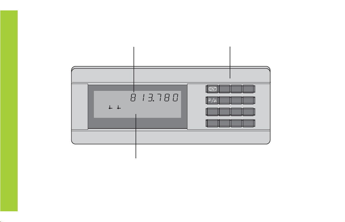
2
Numeric keypad
with decimal point
Status display with indicators
Display of actual value and input
(9 decades with algebraic sign)
HEIDENHAIN
789
456
123
0.CL
MOD
REF SET START PRINT inch
MIN ACTL MAX DIFF
=
<>
21

3
Key Function
• Set datum
• Transfer input value
• Set display to value from P79 (P80!)
• Leave parameter list
• Select datum
• Page backwards in parameter list
• Select parameter after switch-on
• Page forward in parameter list
• Start series of measurements 1)
• Switch display for measurement series 1)
• Start measured value output “PRINT”
• Delete entry
• Set display to zero (P80!)
• CL plus MOD: select parameter list
• CL plus number: select parameter
• Delete parameter input and show
parameter number
• Algebraic sign
• Reduce parameter value
• Decimal point
• Increase parameter value
MOD
1) Only in linear measurement mode.
Indicator Meaning
REF If the decimal point is also blinking:
Display is waiting for reference mark
traversing. If decimal point is not blinking:
Reference mark has been traversed—display
stores datum points in nonvolatile memory
Blinking: display is waiting for ENT or
CL to be depressed
inch Position values in inches
1 / 2 Selected datum point
PRINT "Linear measurement”
Blinking: Display is waiting for ENT to
be pressed for data output
“Angular measurement”
Measured value output with MOD key
SET Blinking: Display is waiting for input values
< / = / > Sorting and tolerance checking:
measured value smaller than lower limit /
within the limits / greater than upper limit
MIN
/
MAX / Series of measurements: Minimum /
maximum / greatest difference (MAX–MIN) /
current measured value
Blinking: Confirm selection or deselect
function
START 1) Series of measurements is running
Blinking: Display is waiting for signal to
start series of measurements
DIFF / ACTL1)

4
Items supplied with ND 281 B
ND 281 B Measured value display unit,
benchtop model
Encoder input
11 µAPP/1 VPP Id. Nr. 344 996-xx
Power cord 3 m (9.9 ft)
User's Manual ND 281B
Adhesive plug-in feet For stacking ND 281B units
This manual is for the ND 281 B measured value
display with the following software number or higher:
349 797-04
The software number is indicated on a label on the
rear panel.
Items Supplied

5
Installation and Specifications
Rear Panel, Accessories 17
Mounting 19
Power Connection 20
Linear/Angular Measuring Modes 21
Operating Parameters 22
List of Operating Parameters 24
Linear Encoders 28
Angle Encoders 33
MultipointAxis Error Compensation 34
Switching Inputs and Outputs EXT (X41) 38
Locking the Keypad 43
Displaying the Software Version 44
Distance-to-Go Mode 45
RS-232-C/V.24 Data Interface (X31) 46
Input/Output of Parameter and 51
Compensation-Value Lists
Output Format of the Parameter List 53
Output Format of the Compensation-ValueTable 57
Remote Operation over the RS-232-C/V.24 60
Data Interface
Specifications 63
Dimensions 64
Contents
Contents
Working with the ND Display Units
Encoders 6
Reference Marks 7
Switch-On,Traversing the Reference Marks 8
Datum Setting 9
Finding Minimum and MaximumValues 1) 10
Sorting andTolerance Checking 13
MeasuredValue Output 14
Display Freeze 15
Error Messages 16
1) Only in linear measurement mode

6
Position Encoders
The ND 281 B display unit is designed for use with photo-
electrical linear or angular encoders with sinusoidal signals:
primarily for HEIDENHAIN MT length gauges.
When shipped by HEIDENHAIN, the display units are set to the
linear measurement mode.
You can switch between the linear and angular modes by
entering the code number 41 52 63 (see “Linear/Angular
Measurement Modes”).
On the back of the display you will find two flange sockets for
connecting the encoder: X1 for encoders with 11 µAPP sinusoi-
dal current signals and X2 for 1 VPP sinusoidal voltage signals.
Before shipping, HEIDENHAIN activates the encoder connec-
tion X1 for 11 µAPP sinusoidal current signals. With parameter
P02 you can activate the encoder input that matches your
encoder (see “Operating Parameters”).
Position Encoders

7
Scale in Distance-coded
linear encoder reference marks
Reference Marks
The MT length gauges have one reference mark. The scales of
other photoelectric linear or angular encoders can contain one
reference mark or many
distance-coded
reference marks.
If there is an interruption of power, the relationship between the
position of the length gauge and the displayed position value is
lost. The reference marks on the position encoders and the REF
reference mark evaluation feature enable the display unit to
quickly reestablish this relationship again when the power is
restored.
When a reference mark is crossed over, a signal is generated
which identifies that position as a reference point. At the same
time, the display unit restores the relationship between length
gauge position and display values which you last defined by
setting the datum.
To restore the datum on scales with distance-coded reference
marks, you only need to traverse a maximum of 20 mm for
linear encoders, and 10° or 20° for angle encoders, depending
on the model.
Reference mark
Reference marks on linear encoders
Reference Marks

8
ENT...CL
Switch-on the reference mark evaluation
function.
• The position value that was last
assigned to the reference mark
position is displayed.
• REF indicator lights.
• Decimal point starts blinking.
5 , 6 9 7
Switch-On, Traversing the Reference Marks REF mode
Crossing over the reference marks automatically switches the
display to REF mode: The last assignment of display values to
length gauge positions is stored in nonvolatile memory.
1) Press the CL key if you choose not to traverse the reference
marks. Note that, in this case, the relationship between
length gauge position and display value will be lost if the
power is interrupted or if the unit is switched off.
Û
Cross over the reference mark.
Move the plunger until the display starts
counting and the decimal point stops blink-
ing. The display is now ready for operation.
0
ä
1
For automation purposes, crossing over the reference marks
and the display ENT ... CL can be disabled with parameter P82.
Switch-On, Traversing the Reference Marks
Turn on the power.
(Switch located on rear panel.)
•ND 281 B appears for two seconds.
•ENT ... CL 1) appears.
• REF indicator starts blinking.

9
Datum Setting
The datum setting procedure assigns a display value to a
known position. With the ND 200 series, you can set two
separate datum points.
There are several ways to set the datum:
• Enter a numerical value, or
• Transfer a value from an operating parameter
(see P79, P80), or
• By external signal
Select datum 1 or 2.
After datum setting: Assignment of measured values to
positions
Without datum setting: unknown assignment of measured
values to positions
Z
?
?
?
?
?
Enter a numerical value (here, 5).
SET starts blinking.
5
You can switch between datums 1 and 2 as desired. Datum 2
can be used, for example, for working with incremental dimen-
sions.
When you switch back to datum 1, the display unit resumes
display of the encoder's actual position.
Datum Setting
Confirmthe entered numerical value.

10
Series of measurements: The MIN, MAX and DIFF values of an
uneven surface
Example: Measurement series for determining eccentricity
e
Finding Minimum and Maximum Values
DIFF
MAX
MIN
ACTL
Finding Minimum and Maximum Values from a
Series of Measurements 1)
After a series of measurements has been started, the display
transfers the first measured value to the memory for minimum
and maximum values. Every 0.55 ms, the display compares the
current measured value with the memory contents: A new
value is stored if it is greater than the stored maximum value or
smaller than the stored minimum value. At the same time, the
display calculates and stores the difference DIFF between the
current MIN and MAX values.
Display Meaning
MIN Minimum value from the series of measurements
MAX Maximum value from the series of measurements
DIFF Difference MAX – MIN
ACTL Current measured value
Starting the measurement series and selecting the display
You can start the series of measurements either by pressing
MOD and selecting the desired display—as described on the
following pages—or by external signal over the switching
inputs at the D-sub connection EXT (X41, see “Switching
Inputs and Outputs”).
When a series of measurements is started, the internal MIN/
MAX/DIFF memory is reset.
1) Only in the linear measurement mode.
Indice
Altri manuali HEIDENHAIN Monitor

HEIDENHAIN
HEIDENHAIN ND 720 Manuale utente

HEIDENHAIN
HEIDENHAIN ND 730 Manuale utente

HEIDENHAIN
HEIDENHAIN VRZ 770 Manuale utente

HEIDENHAIN
HEIDENHAIN ND 261 Manuale utente

HEIDENHAIN
HEIDENHAIN BC 110BF Manuale utente

HEIDENHAIN
HEIDENHAIN VRZ 650 Foglio di istruzioni

HEIDENHAIN
HEIDENHAIN ND 710 Manuale utente

HEIDENHAIN
HEIDENHAIN ND 730 Manuale utente

HEIDENHAIN
HEIDENHAIN BE 411F Manuale utente

HEIDENHAIN
HEIDENHAIN ND 780 Manuale utente


