HID Mercury MR52-S3B Manuale utente

HID®Mercury™ MR52-S3B Reader Interface Installation and Specifications
HID®Mercury™
MR52-S3B Reader Interface
Installation and Specifications
PLT-06451, A.1
September 2023

Copyright
© 2022 - 2023 HID Global Corporation/ASSA ABLOY AB. All rights reserved.
This document may not be reproduced, disseminated or republished in any form without the prior written permission of
HID Global Corporation.
Trademarks
HID GLOBAL, HID, the HID Brick logo, and HIDMercury are trademarks or registered trademarks of HID Global, ASSA
ABLOY AB, or its affiliate(s) in the US and other countries and may not be used without permission. All other trademarks,
service marks, and product or service names are trademarks or registered trademarks of their respective owners.
Contacts
For technical support, please visit: https://support.hidglobal.com.
What's new
Date Description Revision
September 2023 Updated 3.4 Regulatory A.1
A complete list of revisions is available in Revision history.
PLT-06451, A.1 2 September 2023
Powering
Trusted Identities HID®Mercury™ MR52-S3B Reader Interface
Installation and Specifications

Section 01
Overview
1.1 MR52 reader interface
The MR52 reader interface boards provide a solution to the OEM system integrator for interfacing to TTL (D1/D0,
Clock/Data), F/2F, 2-wire RS-485 device and door hardware. The MR52 provides a tristate LED control, and buzzer
control.
Six Form-C relay outputs are provided that can be used for strike control or alarm signaling.
Eight inputs are provided that can be used for monitoring the door contact, request to exit push button, and alarm
contacts. Input circuits can be configured as unsupervised or supervised.
The MR52 communicates to the controller via a 2-wire RS-485.
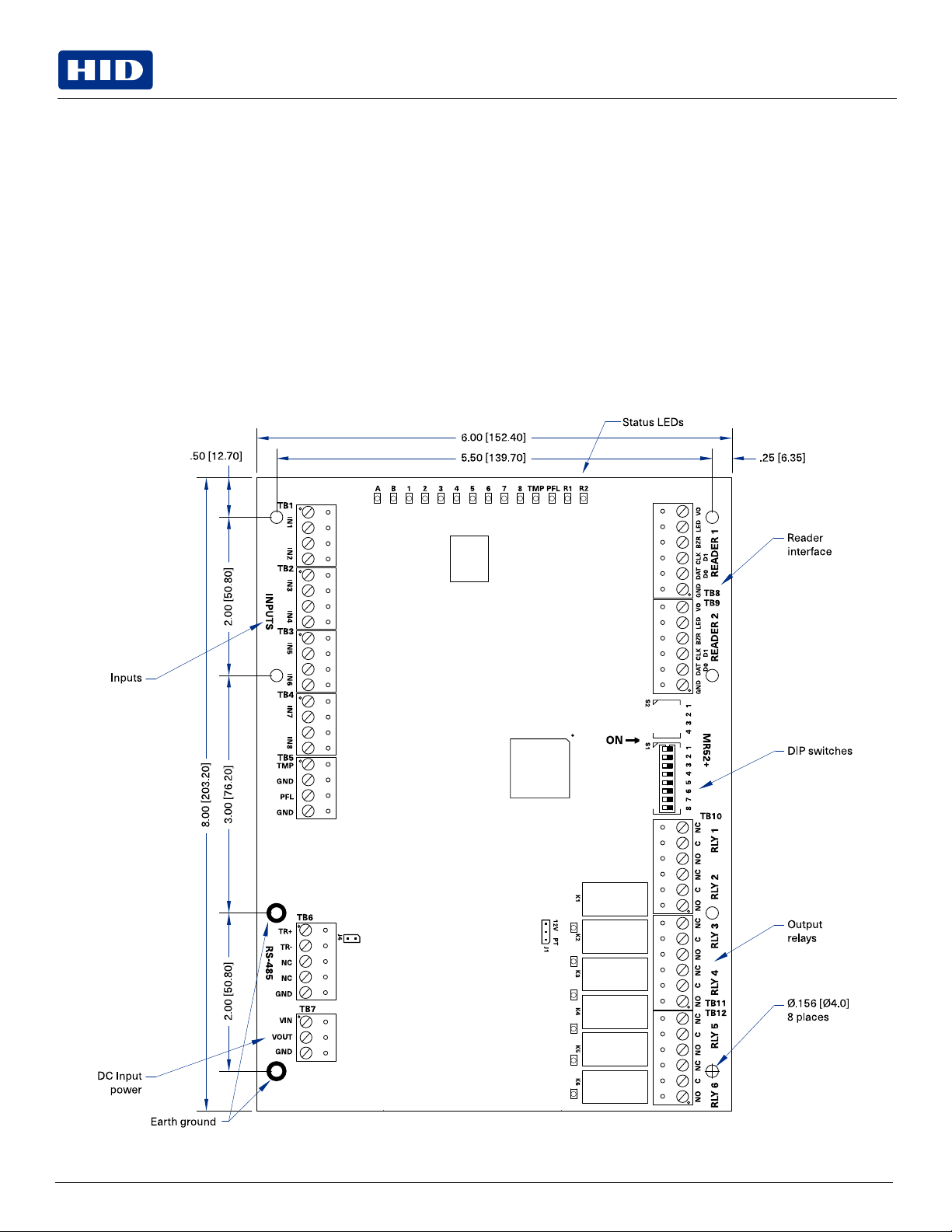
1.1.1 Component location
Some components shown are not present on the MR52.
PLT-06451, A.1 4 September 2023
Powering
Trusted Identities HID®Mercury™ MR52-S3B Reader Interface
Installation and Specifications

Section 02
MR52 wiring and setup
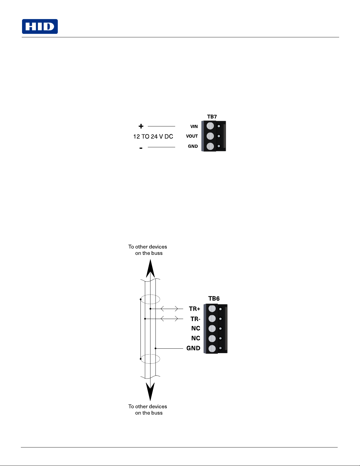
2.1 Supplying power to the MR52
The MR52 accepts 12 to 24 V DC for power on TB7 (VIN and GND). Locate the power source as close to the MR52 as
possible.
Make power connection with minimum of 18 AWG wires.
Observe POLARITY on VIN!
The VOUT terminal on TB7 is the same as VIN.
2.2 Communication wiring (SIO communication port)
The MR52 communicates with a HID Mercury Security intelligent controller (EP2500 for example) via a
2-wire RS-485 interface. The MR52 allows for multi-drop communication on a bus of up to 4,000 feet
(1,200 m). Use twisted pair (minimum 24 AWG) with drain wire and shield for communication.
See Specifications.
Install RS-485 termination jumper, J4, on the interface boards at each end of the communication line only.
2-wire RS-485 TB10
(only 2-wire RS-485 is supported)
PLT-06451, A.1 6 September 2023
Powering
Trusted Identities HID®Mercury™ MR52-S3B Reader Interface
Installation and Specifications
2.3 Reader wiring
Each reader port supports a reader with TTL (D1/D0, Clock/Data), F/2F, or 2-wire RS-485 signaling. Power to the reader
is selectable: 12 V DC (VIN must be greater than 20 V DC), or power is passed-through (PT) from the input voltage of the
MR52 (TB7-VIN), 300 mA maximum per reader port. Readers that require different voltage or have high current
requirements must be powered separately. Refer to the reader manufacture specifications for cabling requirements. In
the 2-wire LED mode the buzzer output is used to drive the second LED. Reader port configuration is set via the host
software.
To fully utilize each reader port:
lTTL signaling requires a 6-conductor cable (18 AWG).
lF/2F signaling requires a 4-conductor cable.
lRS-485 signaling requires two 2-conductor cables. Use one cable for power (18 AWG) and one cable for
communication (24 AWG, with drain wire and shield).
Note:
lFor OSDP cable lengths greater than 200 ft (61 m) or EMF interference, install 120Ω +/- 2Ω resistor across
RS-485 termination ends.
lData 0 and Data 1 wires for Wiegand may be reused for OSDP. However, standard Wiegand cable may not meet
RS-485 twisted pair recommendations. The reuse of cable works best on shorter cable lengths at lower data
rates.
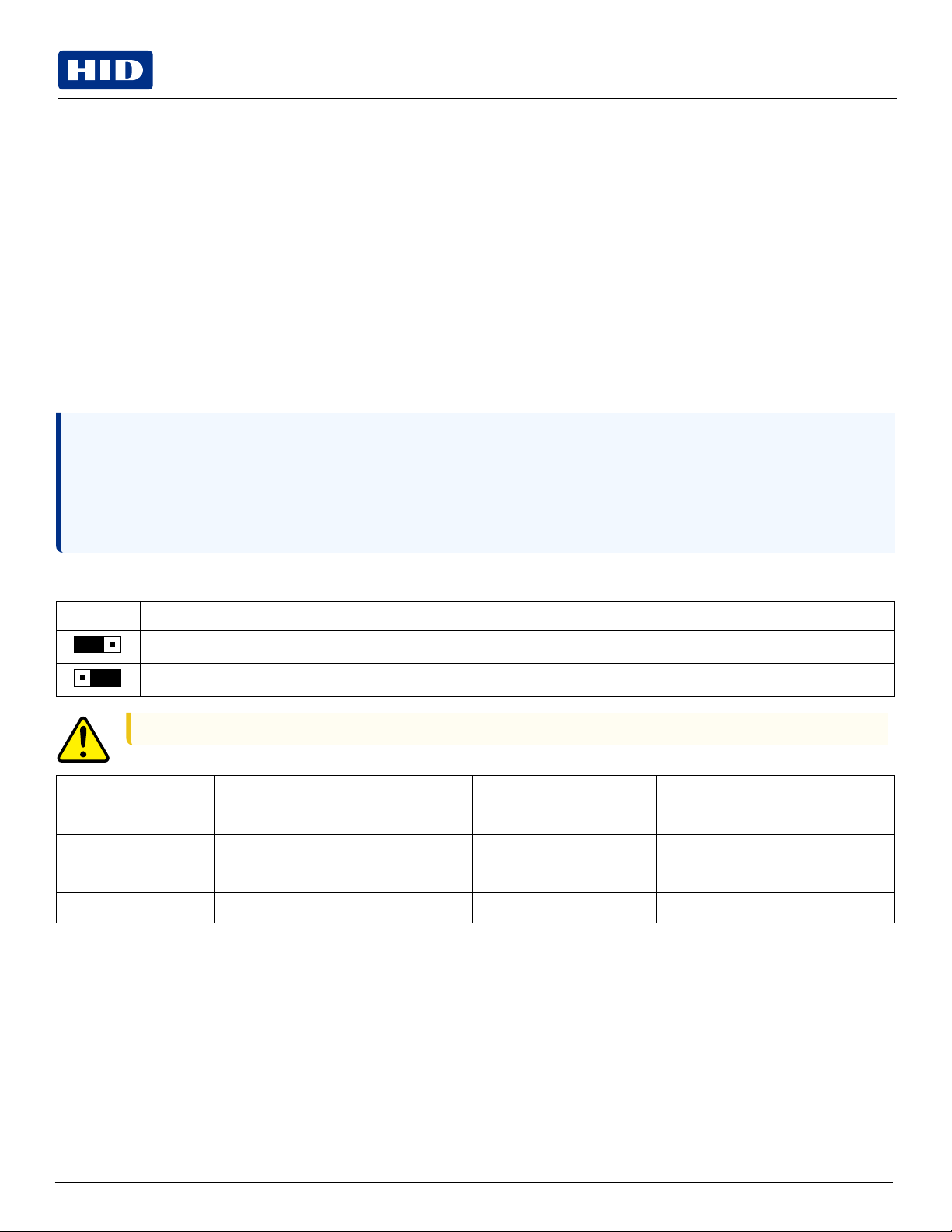
J1 – Reader port power select
12V PT Reader power
12 V DC is available on reader ports (VIN > 20 V DC)
VINpower is "Passed Through" to reader ports
Caution: If the input voltage to the MR52 is 12 V DC, jumper J1 MUST be in the PT position.
Input power Reader power select Reader output Notes
24 V DC Pass-through 24 V DC
24 V DC 12 V DC 12 V DC
12 V DC Pass-through 12 V DC
12 V DC 12 V DC 0 V DC Caution: Do not use
PLT-06451, A.1 7 September 2023
Powering
Trusted Identities HID®Mercury™ MR52-S3B Reader Interface
Installation and Specifications
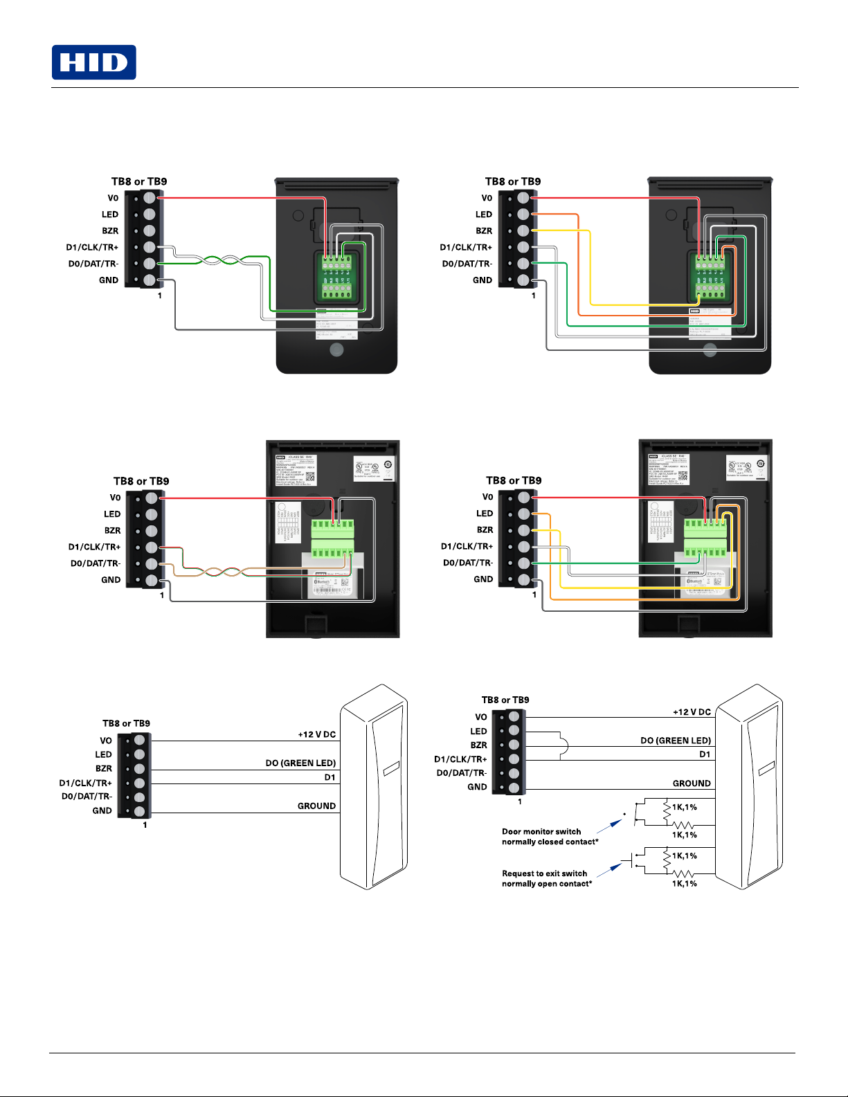
2.3.1 Reader wiring diagrams
Typical reader 1
(OSDP installation)
Typical reader 1
(Wiegand or Clock/Data installation)
Typical reader 2
(OSDP installation)
Typical reader 2
(Wiegand or Clock/Data installation)
Typical Unsupervised F/2F Reader Typical Supervised F/2F Reader
Jumper D1 to LED on supervised F/2F readers
*Inputs on supervised F/2F readers may be unsupervised or supervised (supervised shown).
PLT-06451, A.1 8 September 2023
Powering
Trusted Identities HID®Mercury™ MR52-S3B Reader Interface
Installation and Specifications
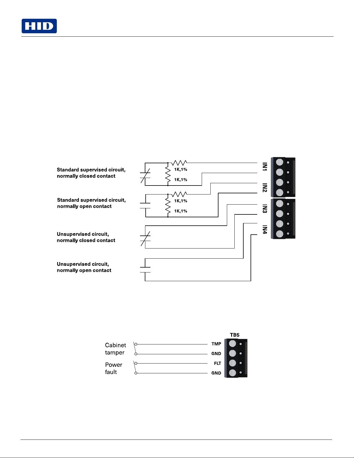
2.4 Alarm contract wiring
There are eight inputs that are typically used to monitor door position, request to exit or alarm contacts. Input circuits can
be configured as:
lUnsupervised alarm (2 states); reporting as open or closed contact.
lSupervised alarm (6 states); reporting as open or closed contact, open circuit, shorted circuit, grounded circuit*, or
foreign voltage*.
A supervised input circuit requires adding two resistors with value of 1kΩ, 1% to the circuit to facilitate proper reporting
and should be located as close to the sensor as possible. Custom end of line (EOL) resistances can be configured via the
host software.
*Grounded and foreign voltage states are not a requirement of UL 294 and therefore not verified by UL.
The input circuit wiring configurations shown are supported but may not be typical:
2.5 Inputs for cabinet tamper/power fault
Input CT and input BA are used for monitoring cabinet tamper and power failure with normally closed contacts. These
two inputs are for contact closure monitoring only, and do not use EOL resistor(s). If these inputs are not used, install a
short piece of wire at the input to indicate a safe condition.
PLT-06451, A.1 9 September 2023
Powering
Trusted Identities HID®Mercury™ MR52-S3B Reader Interface
Installation and Specifications
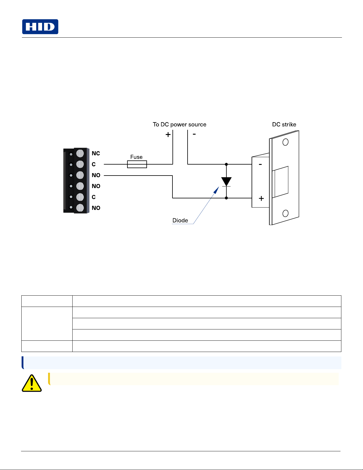
2.6 Control output wiring
Six Form-C contact relays are provided for controlling door strikes or other devices. Load switching can cause abnormal
contact wear and premature contact failure. Switching of inductive loads (strike) also causes EMI (electromagnetic
interference) which may interfere with normal operation of other equipment. To minimize premature contact failure and
to increase system reliability a contact protection circuit must be used. The following two circuits are recommended.
Locate the protection circuit as close to the load as possible (within 12 inches [30 cm]), as the effectiveness of the circuit
will decrease if it is located further away.
Use sufficiently large gauge of wires for the load current to avoid voltage loss.
Diode selection
lDiode current rating > 1x strike current.
lDiode break down voltage: 4x strike voltage.
lFor 12 V DC or 24 V DC strike, diode 1N4002 (100V /1A) typical.
2.7 Jumpers
Jumper Description
J1 Reader power select
12V = 12 V DC at reader ports. See caution below.
PT = VIN “Passed Through" to reader ports
J4 RS-485 termination, install in first and last units only
Note: All other jumpers are for factory use only.
Caution: The input power (VIN) must be 20 V DC minimum if the 12 V DC selection is to be used.
PLT-06451, A.1 10 September 2023
Powering
Trusted Identities HID®Mercury™ MR52-S3B Reader Interface
Installation and Specifications
Indice
Altri manuali HID Controllori di accesso IP


