
HIRED-HAND EVOLUTION BIRD SCALE Manuale utente

Hired Hand Manufacturing, Inc.
1733 County Road 68
PO Box 99
Bremen, Alabama 35033

NOTICE
Every effort has been made to ensure that this manual is complete,
accurate and up-to-date. The information contained in it is
however subject to change without notice due to further
developments.

Part n° 890-00487 rev.00 Evolution Bird Scale Controller 3
1. INTRODUCTION .................................................................. 6
1.1 Precautions, Care & Maintenance .................................... 6
1.2 List of Symbols ............................................................ 7
2. TERMS AND SYMBOLS ........................................................ 8
3. INSTALLATION .................................................................. 9
3.1 Mounting Instructions ..................................................... 9
3.2 Connections .................................................................. 9
3.3 Internal Switches ....................................................... 10
3.4 Voltage Selection ....................................................... 10
4. CONTROLLER'S OPERATION .............................................. 11
4.1 Description of the Controller ......................................... 11
4.2 How to use the Controller ............................................ 11
4.3 Changing Parameter Values .......................................... 11
4.4 How the Parameters are Grouped .................................. 12
4.5 Short-cut keys ........................................................... 12
4.6 Bird Scale Menus ........................................................ 13
5. USING THE CONTROLLER ................................................... 16
5.1 First Installation .......................................................... 16
5.2 Setting the Time and Date ............................................ 17
5.2.1 Viewing the Day of the Week ....................................... 17
5.3 Monitoring Functions ................................................... 18
5.3.1 Scale Information ........................................................ 18
5.3.2 Histories .................................................................... 20
5.3.3 Monitoring the Weight Distribution ................................ 22
5.3.4 Viewing the Current Weight Group Limits ....................... 23
5.3.5 Average Scale Weights ................................................ 24
5.3.5.1 Scale Selection ...................................................... 24
5.3.5.2 Current Average Weights ........................................ 25
5.3.5.3 History ................................................................ 26
5.4 Starting a new flock .................................................... 27
5.5 Weighing Schedule ...................................................... 28
5.5.1 Weighing Day Frequency ............................................. 28
5.5.2 Weighing Times ......................................................... 29
5.6 Enabling / Disabling the Scales ....................................... 30
TABLE OF CONTENTS
Table of Contents

Part n° 890-00487 rev.00 Evolution Bird Scale Controller 4
5.7. Installation settings ..................................................... 31
5.7.1 Entering Password ...................................................... 31
5.7.2 Number of Scales ....................................................... 32
5.7.3 Weight Groups ........................................................... 33
5.7.4 Scale Calibration ......................................................... 37
5.7.5 Other Settings ............................................................ 38
5.7.5.1 Uniformity Bandwidth ............................................ 38
5.7.5.2 Uniformity Error .................................................... 38
5.7.5.3 Correction Factor ................................................... 39
5.7.5.4 Time of Reset ........................................................ 40
5.7.5.5 Weigh Times ........................................................ 40
6. TECHNICAL SPECIFICATIONS ............................................. 41
7. MEMORY CARD ................................................................ 42
8. INDEX ............................................................................. 44
LIST OF FIGURES
Figure 1: Controller's Faceplate ..................................................... 8
Figure 2: Weight groups ............................................................. 33
Figure 3: Absolute Group Size ..................................................... 34
Figure 4: Relative (%) Group Size ................................................. 35
FOR CUSTOMER USE
Enter the serial number located on the side
of the controller below for future reference.
Model number:
Serial number:
EVOLUTION BIRD SCALE

Part n° 890-00487 rev.00 Evolution Bird Scale Controller 5
Limited Warranty
All products are warranted to be free from defects in material and workmanship for a
period of one year from the date of purchase if installed and used in strict accordance
with the installation instructions. Liability is limited to the sale price of any products
proved to be defective or, at manufacturers’ option, to the replacement of such
products upon their return. No products are to be returned to the manufacturer, until
there is an inspection and/or a return-goods authorization (RGA) number is issued.
All complaints should be directed first to the authorized distributor who sold the
product. If satisfaction is not obtained or the name of the distributor is not known,
write the manufacturer that appears below, directed to the attention of Customer
Service Manager. This limited warranty is expressly in lieu of any and all representa-
tions and warranties expressed or implied, including any implied warranty of mer-
chantability or fitness for a particular purpose. The remedy set forth in this limited
warranty shall be the exclusive remedy available to any person. No person has author-
ity to bind the manufacturer to any representation or warranty other than this limited
warranty. The manufacturer shall not be liable for any consequential damages result-
ing from the use of our products or caused by any defect, failure or malfunction of our
products. (Some areas do not allow the exclusion or limitation of incidental or conse-
quential damages, so the above limitation or exclusion may not apply to you.)
This warranty gives you specific legal rights and you may also have other rights that
vary from area to area.
Warrantor:
Hired-Hand MFG., Inc.
1733 County Road 68
PO Box 99
Bremen, Alabama 35033
Part n° 890-00487 rev.00 Evolution Bird Scale Controller 6
1. INTRODUCTION
1.1 Precautions, Care & Maintenance
WARNING:
Read and save
these instructions!
Safety may be jeopardized if the equipment is used in a manner not speci-
fied by the manufacturer. Carefully read and keep the following instruc-
tions for future reference.
• Although fuses at the input and outputs of the controller protect its
circuits in case of an overload or overvoltage, we recommend install-
ing an additional protection device on the controller's supply circuit.
• The room temperature where the controller is located must always
remain between 32 °F and 104 °F (0 °C to 40 °C). For Indoor use
only !
• To avoid exposing the controller to harmful gases or excessive humidity,
it is preferable to install it in a corridor.
•Do not spray water on the controller! In order to clean the control,
wipe it with a damp cloth.
Before servicing or cleaning unit, switch power off at service
panel and lock the switch disconnecting means to prevent
power from being switched accidentally. When the service
disconnecting means cannot be locked, securely fasten a
prominent warning device, such as a tag, to the service panel.
• The controller should be opened and inspected once a year for mois-
ture. Proper care will extend the life of the control.

Part n° 890-00487 rev.00 Evolution Bird Scale Controller 7
1.2 List of Symbols
Warning. Read the following text carefully; it contains impor-
tant information which, if ignored, may cause the controller to
operate improperly.
High Voltage. Hazard of electrical shock. Read the message
and follow the instructions carefully.
Pay attention. The following text contains very useful informa-
tion.
Double insulation.
Both direct and alternating current
(AC/DC).
Direct current (DC).
Alternating current (AC).
Earth Ground Terminal
Primarily used for functional earth terminals which are gener-
ally associated with test and measurement circuits. These
terminals are not for safety earthing purposes but provide an
earth reference point.
Part n° 890-00487 rev.00 Evolution Bird Scale Controller 8
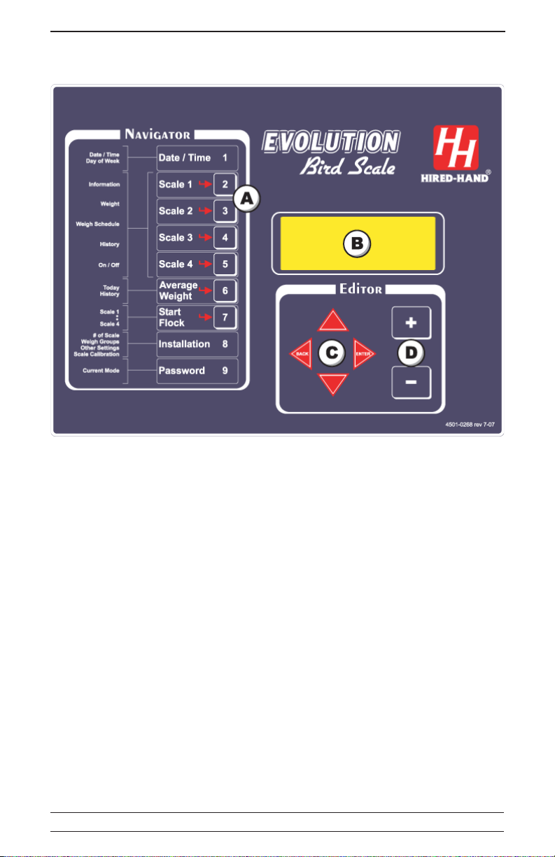
AShortcut Keys. These 6 buttons allow quickly stepping to special pre-
set functions.
BDisplay. This screen displays the various parameters and readings.
CArrow keys. The up and down arrow keys are used to scroll the menus.
The right arrow key is used to select a menu option and the left arrow
key is used to return to the previous menu display.
DAdjustment Buttons. These two push-buttons are used to modify the
value of a parameter.
2. TERMS AND SYMBOLS
Figure 1: Controller's Faceplate

Part n° 890-00487 rev.00 Evolution Bird Scale Controller 9
3. INSTALLATION
3.1 Mounting Instructions
Open the latch and lift the cover. Remove the black caps located on each
of the four mounting holes. Mount the enclosure on the wall using four
screws. Be sure the electrical knockouts are at the bottom of the enclo-
sure in order to prevent water from entering the controller. Insert the
screws in the mounting holes and tighten. Fasten the four black caps
provided with the controller onto the four mounting holes. The enclosure
must be mounted in a location that will allow the cover to be completely
opened right up against the wall.
3.2 Connections
To connect the controller, refer to the wiring diagram enclosed with this
user's manual. Use the electrical knockouts provided at the bottom of the
enclosure. Do not make additional holes in the enclosure, particularly on
the side of the enclosure when using a computer communications module.
Refer to the wiring diagram enclosed with this user's manual to connect
the controller. Use the electrical knockouts provided at the bottom of the
enclosure. Do not make additional holes in the enclosure, particularly on
the side of the enclosure when using a computer communication module.
All wiring must be done by an authorized electrician and must
comply with applicable codes, laws and regulations. Be sure
power is off before doing any wiring to avoid electrical shocks
and equipment damage.
Do not install rigid conduit into electrical knockouts. Only nylon
cable glands are permitted for cable or wire fastening.
The controller has no power-on switch. An external switch or
circuit breaker shall be included in the building installation to
interrupt power to L and N electric power lines. It shall be in
close proximity to the equipment and within easy reach of the
operator. It shall be marked as the disconnecting device for the
equipment.

Part n° 890-00487 rev.00 Evolution Bird Scale Controller 10
#FFONO
1SMARGSDNUOP
21-2DESUTON
ON
OFF
121110987654321
3.3 Internal Switches
The internal switches are located
inside of the front cover of the con-
troller. When the controller is shipped
from the factory, all the switches are
set to OFF.
3.4 Voltage Selection
If a voltage switch is located on the electronic circuit
board of the controller, set it to the corresponding power
supply (115 or 230 V).
Indice
Altri manuali HIRED-HAND Controllori


