Hochiki SPC-E Manuale di istruzioni per l'installazione

SPC-E Mounting Guidelines Page 1
Hochiki Europe (UK) Ltd 2-3-0-798/ISS2/MAR08
SPC-E PHOTOELECTRIC BEAM DETECTOR
MOUNTING GUIDELINES
When installing the SPC-E Beam Detectors, it is important that the following guidelines are adhered to:
Do not mount in locations that are exposed to
extremely high temperatures or water vapour.
Do not mount SPC-E within 300mm of any
obstruction.
Do not mount where the distance between the
Emitter and Receiver is less than 5 metres or greater
than 100 metres.
Make sure the surface that the SPC-E units are to
be mounted on is rigid (ideally part of the building
structure) to avoid any possibility of movement.
When fixing the SPC-E allow enough space to gain
access to the sight hole for aligning purposes (this is
located on the top right hand side of the Receiver
unit, when viewed from the front).
List of Parts
The SPC-E Beam Detector kit consists of three separate parts:
SPC-E Receiver and Emitter.
2 x four pronged Mounting Plates.
Test Filters (25%, 50% and 60%).
Mounting the SPC-E Beam Detectors
The SPC-E Beam Detectors are designed to mount vertically onto the four pronged mounting brackets supplied. These
brackets should be fixed securely to the wall and directly opposite each other, they must also be mounted in the same
horizontal plane.
There are several wiring methods available for the SPC-E, all of which are further explained in our Application Note
AP097 available from our website. The most common wiring method is shown below. In all methods, cables should be
brought through the top of the back box, and terminated into the appropriate connector blocks. The SPC-E Beam
Detectors require the use of an auxiliary 24Vd.c. Power Supply Unit (not supplied). The Power Supply and field wiring
should be terminated into the front of the SPC-E. Refer to Fig.1 if the panel requires a short-circuit to produce a fire
condition. If the panel requires a fire resistor refer to Fig 2.
Fig.1
Note: The Emitter can be powered directly from a local 24Vd.c. power supply, the Conventional zone or an ESP loop.

SPC-E Mounting Guidelines Page 2
Hochiki Europe (UK) Ltd 2-3-0-798/ISS2/MAR08
Starting at the emitter end, the cover
should be opened (refer to Fig.3.)
the field wiring can then be
connected either from behind the
detector or from below the detector,
depending on the suitability of the
installation. If the wires are to come
in from below, then it will be
necessary to break the knock-out
slot from the bottom of the detector
body (located near to the retaining
clip).
Fig.2
Hook the back of the detector body to the 4 prongs of the mounting plate and slide down firmly, ensuring that the cables
are not trapped or damaged by the detector.
The stripped wires should be pushed into the holes of the connector whilst the white push key is pressed with a small
screwdriver, this will enable the wire to push completely home, the white push key can then be released, and this should
then grip the cable securely.
The Receiver
should then be
connected next.
Firstly open the
Receiver cover
(refer to Fig.3.)
and then connect
the field wiring
either from behind
or below the
detector,
depending on the
suitability of the
installation.
The Receiver
can then be
mounted onto
the Interface kit
by aligning the
four mounting
slots on the rear
of the Receiver
with the four
mounting hooks
on the mounting
bracket and then
sliding the
Receiver down
gently. The
cables should be
terminated as
shown in Fig.1.
or Fig.2.
Fig.3

SPC-E Mounting Guidelines Page 3
Hochiki Europe (UK) Ltd 2-3-0-798/ISS2/MAR08
Setting up the SPC-E
Once power has been applied
(24VDC) the Beam Detector can now
be aligned. The covers on both the
Emitter and Receiver need to be
open. The green polling LED on the
Receiver should now be flashing once
per 3 seconds, but please note the
units require between 30 and 60
seconds to fully power-up.
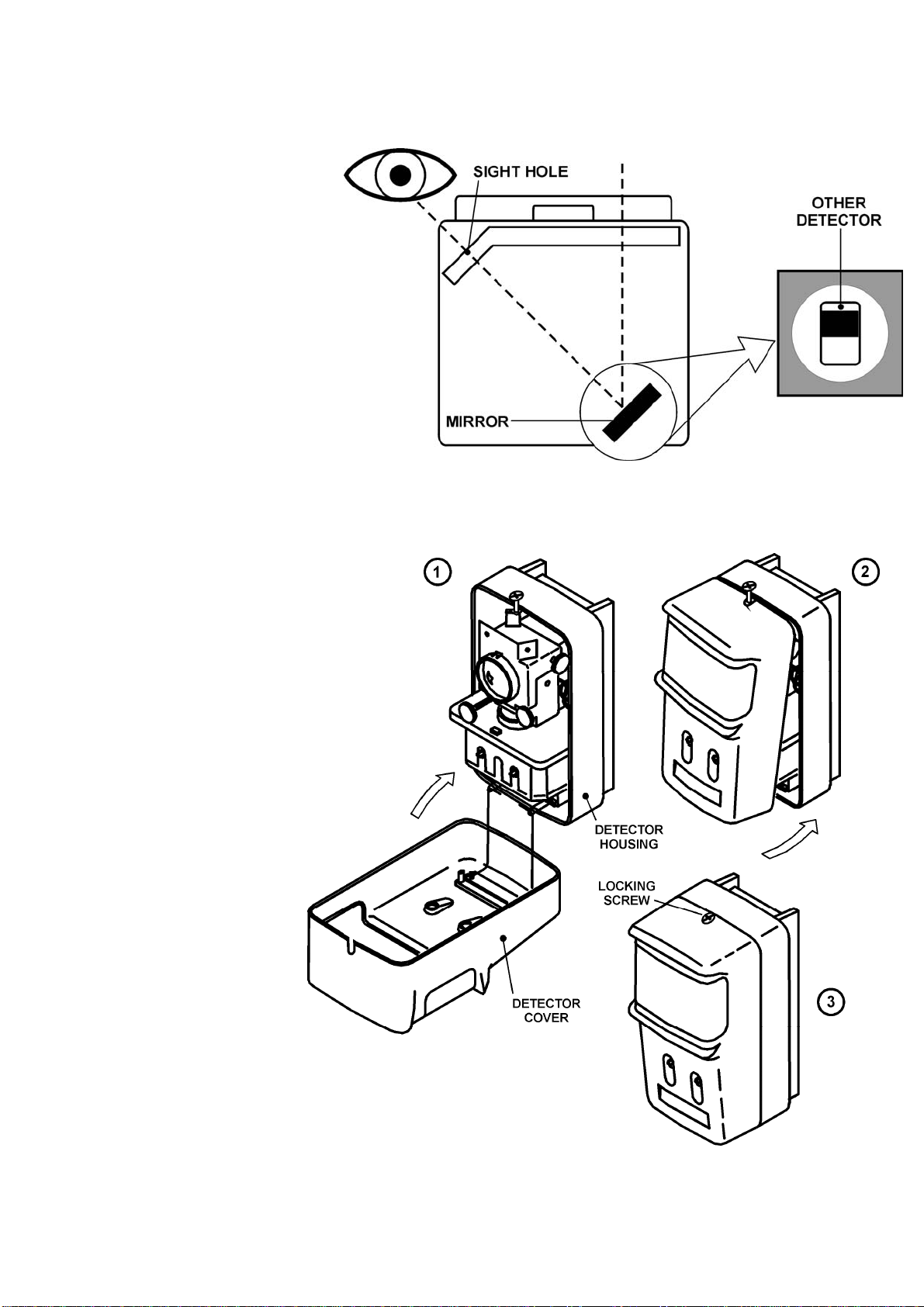
On the top right of the Receiver there
is a sight hole, when looking through
this the Emitter should be clearly
visible in the centre of this hole
(please refer to Fig.4.). If it isn’t, then
using the silver alignment wheels (left
wheel horizontal adjustment, right
wheel vertical adjustment) the
Receiver should be adjusted until the
Emitter is clearly visible.
Fig.4
This procedure should then be repeated at the Emitter end. Set the distance switch on the emitter according to the
monitoring distance and close the cover of the emitter. Close the cover, then fasten the locking screw, refer to Fig.5.
Once this has been achieved
the 4-part DIP switch needs to
be set. Bits 1 and 2 are set
according to which signal
strength is required; there are
three choices available, 25%,
50% and 60%.
Bit 3 can be set to switch the
signals to be emitted when the
beam is blocked to fault and
fire(OFF), or to fault alone(ON).
Bit 4 can be set to switch
between the automatic(OFF) or
manual(ON) recovery from the
fault status. Please note that if
the SPC-ET is set to show a
non-latching fault on total
obscuration, and the SPC-ET
beam is blocked for more than
30 minutes then the fault will
LATCH. To remove this fault
the SPC-ET will need to be
powered down, or the receiver
cover will need to be opened
and then closed to re-
synchronise the receiver with
the emitter.
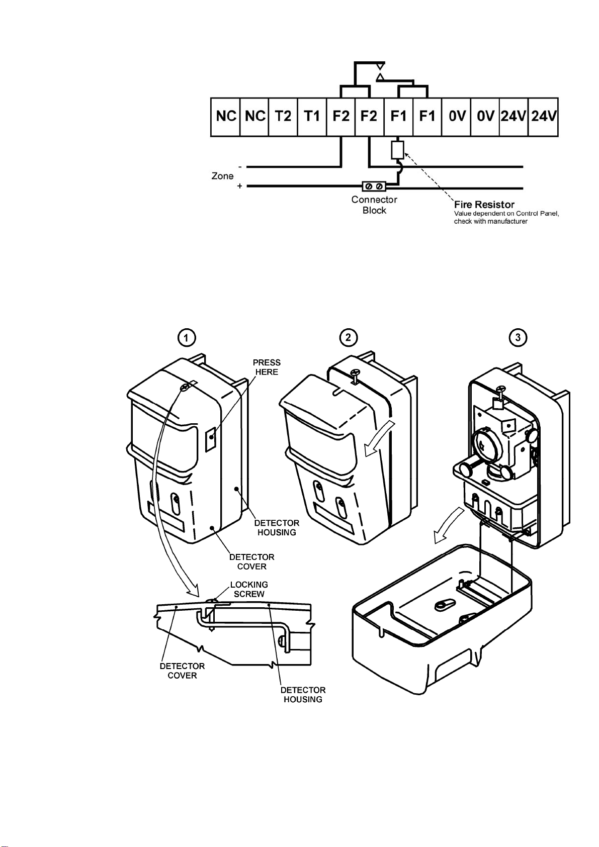
The cover on the Receiver can
now be closed (please refer to
Fig.5.), this should be done
carefully, avoiding the possibility
of moving the SPC-E out of
alignment.
Fig.5
Closing the cover on the receiver synchronizes the receiver with the emitter, then automatically adjusts the
amplification factor of the reception circuit, then initiates fire monitoring.

SPC-E Mounting Guidelines Page 4
Hochiki Europe (UK) Ltd 2-3-0-798/ISS2/MAR08
While synchronization is being established with the emitter and while the reception signal level is automatically
adjusted, the monitor lamp (green) and fault lamp (yellow) on the receiver blink at intervals of three seconds. If the
system shifts successfully to the monitoring state, the monitor lamp (green) alone will blink. It takes about two minutes
for fire monitoring to begin after the receiver cover is closed. In the meantime, take care not to block the beam. Once
this has completed the cover should be locked in place with the supplied locking screw (please refer to Fig.5).
After the SPC-E has completed its initialisation it should be tested using the filters supplied. The range 1 filter relates to
25%, the range 2 filter relates to 50% and the range 3 filter relates to 60%. Firstly place the no alarm side of the filter in
front of the SPC-E for at least one minute this should cause no fire or fault signals, if a fault occurs the amber LED will
flash once every 3 seconds. Next place the alarm side of the filter in front of the SPC-E for at least one minute. During
this time a fire alarm should occur and the red LED should illuminate continuously, if no alarm occurs, then the SPC-E is
not operating as expected.
Installation Data
Allowable Misalignment Angle
Emitter ± 0.5° (max)
Receiver ± 1.0° (max)
Guide Settings
Range Sensitivity
5 ~10m 25% (1.25 dB)
10 ~ 100m 50% (3.01 dB)
Approved Settings
The SPC-E is EN54-12:2002 approved at the 25% and 50% sensitivity settings.
Hochiki Europe (UK) Ltd
Grosvenor Road, Gillingham Business Park,
Gillingham, Kent, ME8 0SA, England
Telephone: +44(0)1634 260133 Facsimile: +44(0)1634 260132
Email: sales@hochikieurope.com
Web: www.hochikieurope.com
Hochiki Europe (UK) Ltd. reserves the right to alter the specification of its products from time to time without notice. Although every effort has been
made to ensure the accuracy of the information contained within this document it is not warranted or represented by Hochiki Europe (UK) Ltd. to be
a complete and up-to-date description. Please check our web site for the latest version of this document.
Indice
Altri manuali Hochiki Sensore di sicurezza

Hochiki
Hochiki RHD-E-AS Manuale utente

Hochiki
Hochiki IFD-E Manuale utente

Hochiki
Hochiki DFG-60E Manuale utente

Hochiki
Hochiki SPC-ET Manuale di istruzioni

Hochiki
Hochiki FIRElink-100 Manuale utente

Hochiki
Hochiki DH-100-P Manuale utente

Hochiki
Hochiki FIRElink-25 Manuale utente

Hochiki
Hochiki YBO-BS Manuale utente

Hochiki
Hochiki IFD-E(Exd) Manuale utente


