Hoffmann&Hoffmann Dripmaster EDD-4C Manuale utente

Copyright ©2010 Hoffmann & Hoffmann Ltd. Rev. 04, May 2010
1
Dripmaster EDD-4C
U.S. Patent No. 5,996,739 & other countries
User Guide
Document filename: Dripmaster_EDD-4C_User_Guide_18May10.doc
Important notice: Hoffmann & Hoffmann reserves the right to change this document without further notice due
to design improvements, functional modifications or quality/reliability amendments.
2
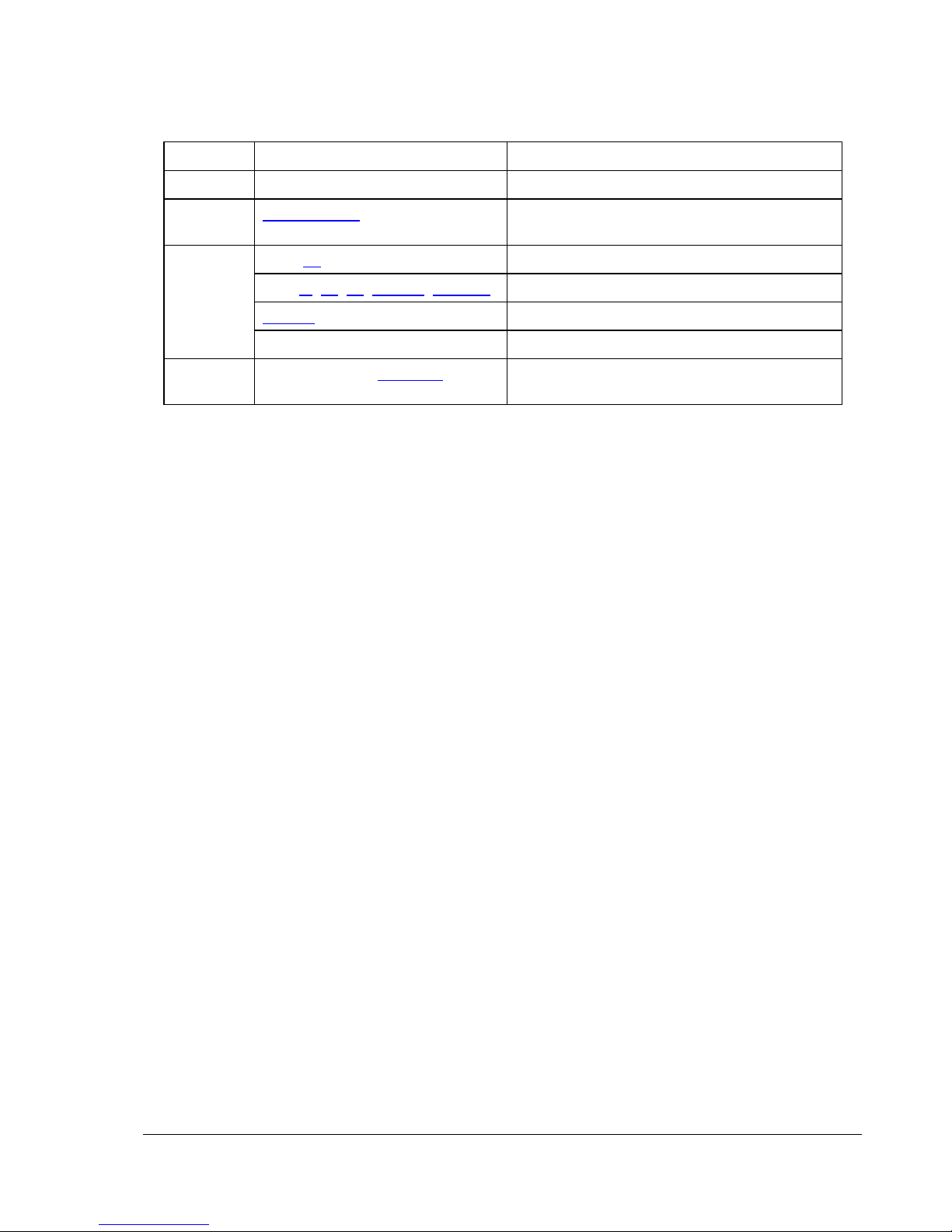
Revision History
Revision Section Notes
01 – Initial document
02 Installation Kit on page 9 Deleted ¼-inch fuel hose as part of
installation kit
Page 18 Third line of text: ...flow switch to the right...
Page 7, 10, 22, Table 1, Figure 9 Line power includes 220 VAC
Table 6 Updated specifications
03
Last page Updated contact information
04 Cover page and Section 7. Updated company logo and contact
information

3
Contents
Section 1: Introduction ............................................................................................................................... 5
Overview .......................................................................................................................................... 5
Section 2: Installation ................................................................................................................................. 7
General............................................................................................................................................. 7
Well Site Requirements.................................................................................................................... 7
Installation Kit................................................................................................................................... 9
Mounting the Dripmaster.................................................................................................................. 9
Wiring the Power and Control Cables............................................................................................ 10
Setting the Drip Rate...................................................................................................................... 12
Section 3: Operation ................................................................................................................................ 13
Controls and Indicators .................................................................................................................. 13
Automatic Control........................................................................................................................... 16
Setting Normal (pump on) Mode Drip Rates ....................................................................... 16
Pre-lube (pump off) Mode.................................................................................................... 17
Manual Control............................................................................................................................... 17
Resetting the Dripmaster ............................................................................................................... 18
Section 4: Theory of Operation ................................................................................................................ 19
General........................................................................................................................................... 19
Search Feature .............................................................................................................................. 21
Push-Down and Push-up Features................................................................................................ 22
Section 5: Maintenance and Troubleshooting.......................................................................................... 23
Section 6: Specifications .......................................................................................................................... 25
Overall Dimensions ........................................................................................................................ 26
Section 7: Dripmaster Service Policy....................................................................................................... 27
Installation ...................................................................................................................................... 27
Repair procedure ........................................................................................................................... 27
Product within the Warranty Period ............................................................................................... 28
Product Out-of-Warranty Period .................................................................................................... 28
Return Instructions ......................................................................................................................... 28
Terms & Conditions on reverse ..................................................................................................... 29

4
List of Figures
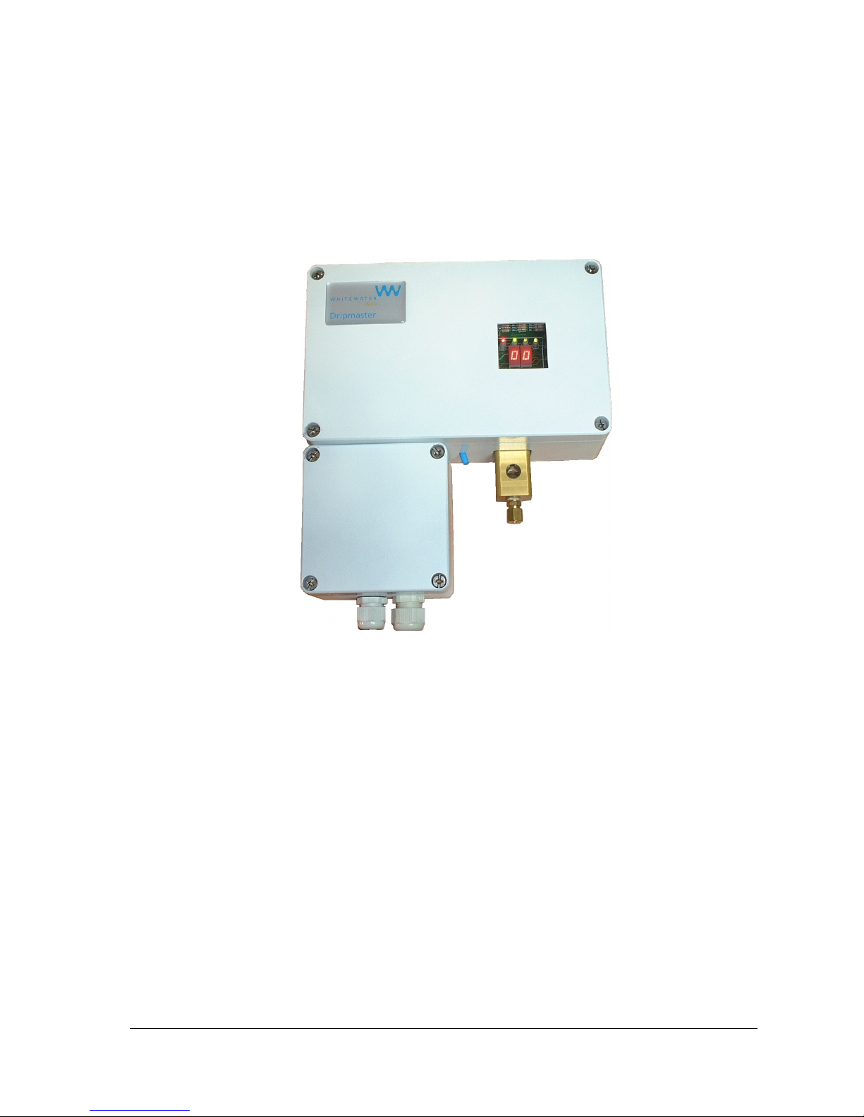
Figure 1: Dripmaster EDD-4C............................................................................................................... 5
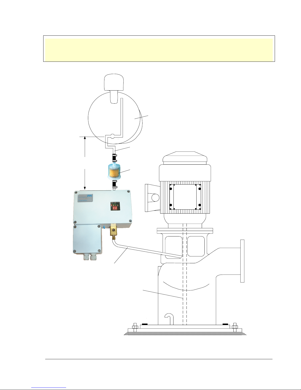
Figure 2: Installation requirements ....................................................................................................... 8
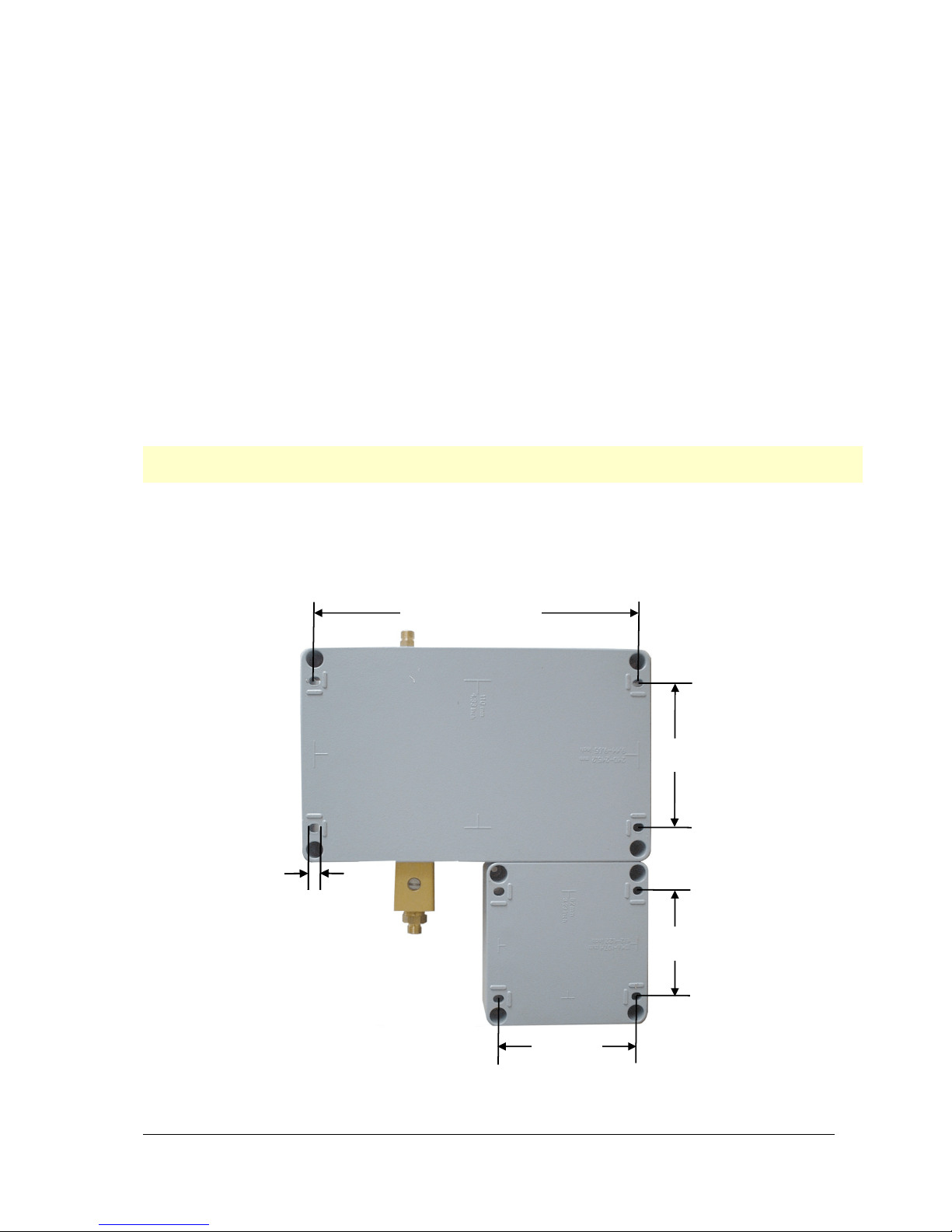
Figure 3: Dripmaster—rear view showing mounting centers................................................................ 9
Figure 4: Connection box – cable routing........................................................................................... 10
Figure 5: Connection box – electrical terminals: 115 VAC unit shown............................................... 10
Figure 6: Dripmaster control panel ..................................................................................................... 13
Figure 7: Dripmaster EDD-4C Needle Valve Assembly ..................................................................... 18
Figure 8: Common Needle Valve compared to Dripmaster................................................................ 19
Figure 9: Dripmaster functional diagram ............................................................................................ 20
Figure 10: Dripmaster EDD-4C Needle Valve Assembly ................................................................... 21
Figure 11: Dripmaster dimensions...................................................................................................... 26
List of Tables
Table 1: Connection box—power and control lines............................................................................ 11
Table 2: Pump On/Off conditions ....................................................................................................... 12
Table 3: Control panel—controls and indicators................................................................................. 13
Table 4: Routine Maintenance............................................................................................................ 23
Table 5: Troubleshooting .................................................................................................................... 23
Table 6: Dripmaster EDD-4C specifications .......................................................................................25
5
Section 1: Introduction
Overview
The Dripmaster is an active vertical line-shaft lubrication control and monitoring device. It
automatically stabilizes the oil drip rate so as to comply with pump manufacturer's requirements.
Figure 1: Dripmaster EDD-4C
Constant drip rate is maintained regardless of ambient temperature or hydrostatic pressure in the
feeding oil tank. This is achieved by monitoring and controlling the drip rate 55 times per hour.
There are two modes of operation:
•Normal (pump on) mode—when the well pump is operational
•Pre-lube (pump off) mode—ensures that the line-shaft is lubricated prior to turning on the well
pump.
Automatic switching between the Normal (pump on) and Pre-lube (pump off) modes is achieved by
remotely sending a control signal to the Dripmaster.
The SCADA interface provides:
•Accurate oil consumption data (drip rate count)
•Total lack of oil warning
•Automatic pump shutdown
A built-in manual mechanism ensures oil flow even in the remote possibility of unit malfunction.

6
End of section

7
Section 2: Installation
General
The Dripmaster installation procedure is simple and does not require any special tools, but requires
site preparation.
Well Site Requirements
•Line power (115 VAC or 220 VAC), or 24 V AC/DC must be available at the well pump.
•An eight-wire control cable (containing wires not smaller than 22 AWG) needs to be laid
between the well pump and the local PLC enclosure.
•A sturdy, vertical pole with a welded metal plate should be in close proximity to the well pump.
Note: For large oil tanks (35 to 50 gallons), mount the Dripmaster to the oil tank stand.
8
Important: The relative spacing between the oil tank, the Dripmaster, and the line-shaft inlet should be
according to Figure 2. In order to maintain minimal oil pressure on the needle valve
(especially when the oil tank is almost empty), the oil inlet should be in the range of 10 to 14
inches below the oil tank.
10 to 14 inches
(25.4 to 35.6 cm)
1/4-inch
(0.635 cm)
copper pipe
Oil filter
Oil tank
1/4-inch flexible
copper tubing
Lineshaft
Figure 2: Installation requirements
9
Installation Kit
The Dripmaster is supplied with the following parts:
1 – oil filter (fuel filter for ¼-inch hose)
4 – mounting bolts
8 – nuts
8 – lock washers
2 – cable bushings (glands)
Make sure that all of the kit items are present. You need to obtain ¼-inch fuel hose to complete the
installation.
Mounting the Dripmaster
1. In order to mount the Dripmaster, drill four 1/4-inch holes in the metal plate that mounts the
Dripmaster according to the drilling template shown in Figure 3.
Note: The mounting centers for the Dripmaster are shown on the back of the unit for convenience.
Mounting the unit does not require more than four bolts.
2. Remove the Dripmaster front covers.
3. Place a bolt into a mounting hole, and keep it in place by using a nut.
4. Repeat step 3 for the other bolts.
5. Secure the device to the metal plate using the remaining nuts and lock washers.
9.55 inches (242.6 mm)
4.17 inches
(106 mm)
3.23 inches
(82 mm)
4.33 inches
(110 mm)
0.25 inches
(6.4 mm)
Figure 3: Dripmaster—rear view showing mounting centers

10
Wiring the Power and Control Cables
Power and control cables are routed through the bottom of the connection box through two strain
relief bushings.
Power cable entry Control cable entry
Green ground wire
connects here
Figure 4: Connection box – cable routing
Wire the connection box according to Figure 5. Connections are described in detail in Table 1 on
page 11.
Control
cable
Power
cable
115 VAC
or
24 VAC/VDC
24VAC/DC S.B. - Pre-lube (pump off) mode
LL - Total lack of oil
PULSE - Drip indication
O.K.
. - Sufficient lubrication
I
I
J
J
J
J
J
J
Voltage selector switch SW1:
115 VAC / 24 V AC/DC
Note: The pump can be optionally
wired to shut down when the O.K.
relay contacts open.
Figure 5: Connection box – electrical terminals: 115 VAC unit shown
1. Set the power switch SW1 located just below the transformer, for line power (115 VAC or
220 VAC) or 24 V AC/DC according to your requirements. See Figure 5.
Indice
Manuali Pompa dell'acqua popolari di altre marche


Sykes AmeriPumps
Sykes AmeriPumps GP100M Guida alla risoluzione dei problemi

DUROMAX
DUROMAX XP WX Series Manuale utente

BRINKMANN PUMPS
BRINKMANN PUMPS SBF550 Manuale utente

Franklin Electric
Franklin Electric IPS Manuale utente

Xylem
Xylem e-1532 Series Manuale utente

Milton Roy
Milton Roy PRIMEROYAL Manuale utente