XL-TG10149IM-en-US Rev A 12-10 Amendments and Errors Reserved. © SAF-HOLLAND, Inc.
Introduction......................................................................2
Warranty...........................................................................2
Notes, Cautions, and Warnings..........................................2
Section 1 – Safety Precautions..........................................3
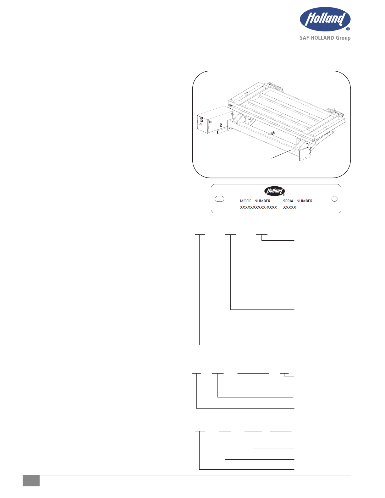
Section 2 – Model and Serial Number Location..................6
Section 3 – Liftgate Terminology………………….……………...7
Section 4—Frame Preparation……………………………………..8
Section 5—Deck Extension Installation………………………..10
Section 6—Liftgate Installation…………………………………. 11
Section 7– Pump Assembly Installation……………………… 14
Section 8– Hydraulic Hose Installation…………………...…..16
Section 9– Toggle Installation……………….. …………………17
Section 10– Electrical Installation…………………….……....18
Section 11– Auxiliary Battery Electrical Installation……..…..20
Section 12– Initial Platform Lowering…………..………………..22
Section 13– Return Spring Installation...………………………..23
Section 14– Latch Pin Installation……………………….………..23
Section 15– Step Installation……………..………………………..24
Section 16– Roller Opener Installation……………...…………..25
Section 17– Decal Installation……………...……………………..26
This manual provides you with the information necessary
for the installation of the SAF-HOLLAND TG Series Liftgate.
Refer to the complete warranty for the country in which the
product will be used. A copy of the warranty certificate is
included with the product as well as on the SAF-HOLLAND
Web Site (www.safholland.us and www.safholland.ca).
Notes, Cautions and Warnings
You must read and understand all of the safety procedures
presented in this manual before starting any work on the
liftgate.
For liftgate components replacement, contact
SAF-HOLLAND Customer Service at:
U.S. 1-888-396-6501
Canada 1-800-503-9847.
In the United States, work shop safety
requirements are defined by federal and/or
state Occupational Safety and Health Act.
Equivalent laws may exist in other countries.
This manual is written based on the
assumption that OSHA or other applicable
employee safety regulations are followed by
the location where work is performed.
Used without the safety alert symbol,
indicates a potentially hazardous situation
which, if not avoided, may result in property
damage.
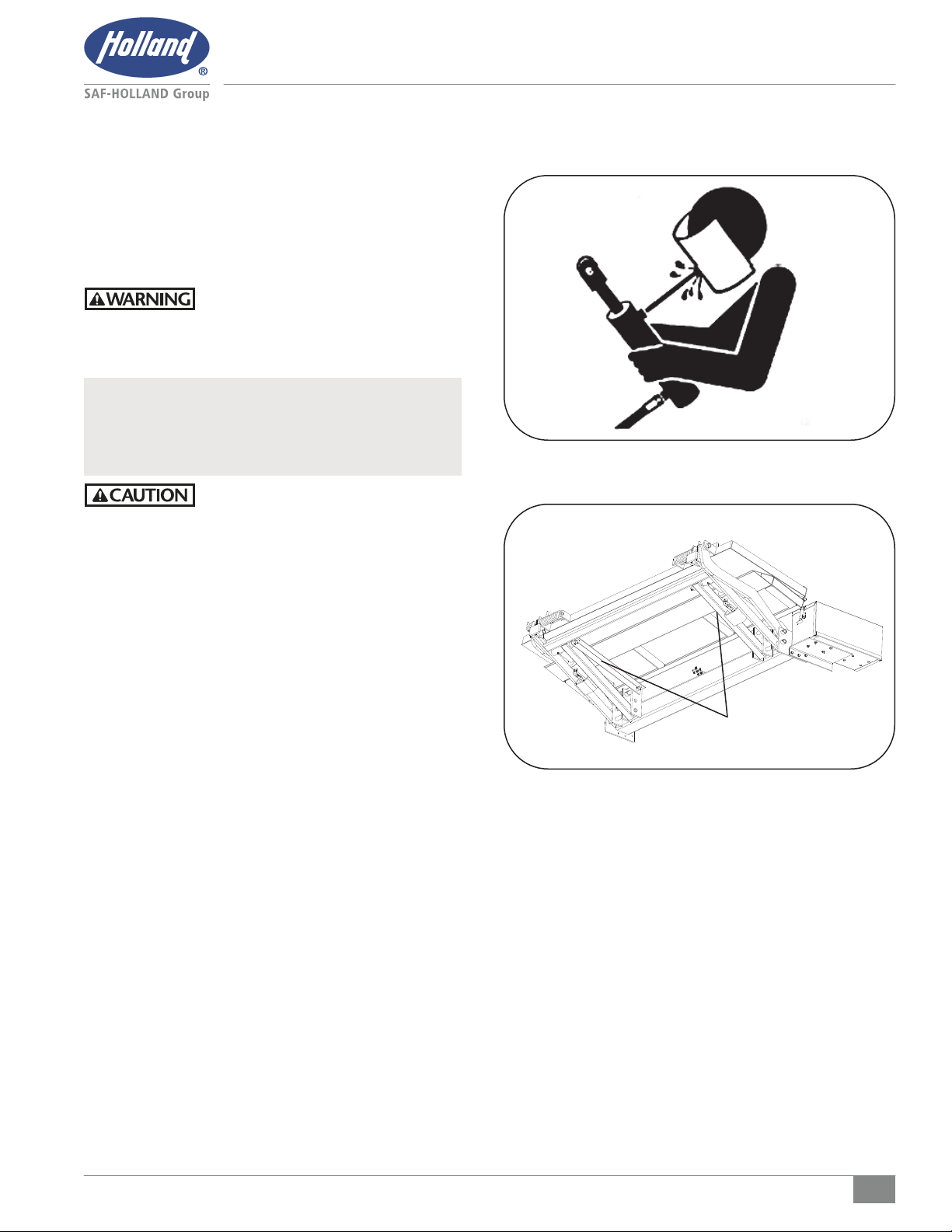
Indicates a potentially hazardous situation
which, if not avoided, may result in minor or
moderate injury.
Indicates a potentially hazardous situation
which, if not avoided, could result in death
or serious injury.
Includes additional information that if
not followed could lead to hindered
product performance.
Includes additional information to enable
accurate and easy performance of
procedures.
Throughout this manual, you will notice the terms “NOTE,”
“IMPORTANT,” “CAUTION,” and “WARNING,” followed by
important product information. So that you may better
understand the manual, these terms are as follows: