Honeywell T7770A Manuale utente
INSTALLATION INSTRUCTIONS
® U.S. Registered Trademark
© 2004 Honeywell International Inc.
All Rights Reserved 95-7538—4
T7770A,B,C,D,E,F,G
Wall Modules
BEFORE INSTALLATION
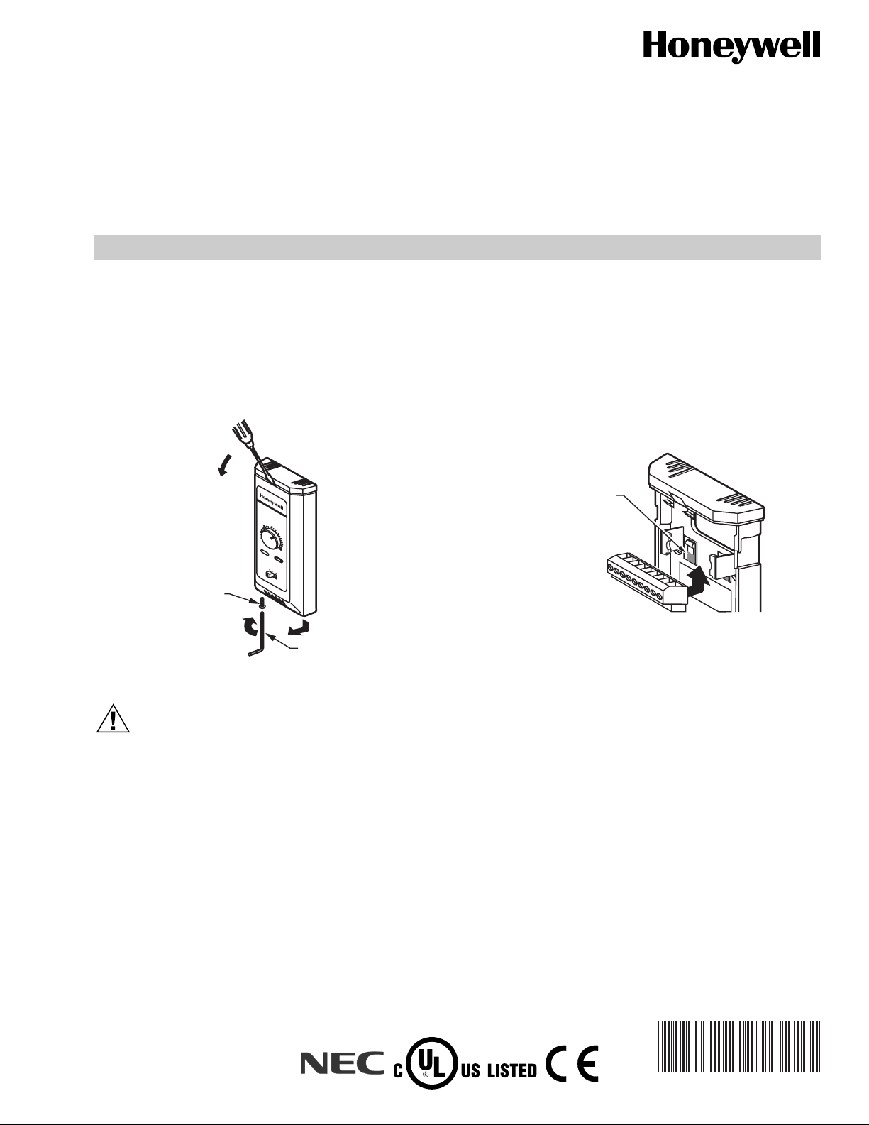
Cover Disassembly
Two locking mechanisms are used on the cover of the wall
module. After installation, to disassemble the cover and the
subbase see Fig. 1.
Fig. 1. Cover disassembly.
CAUTION
Erratic System Operation Hazard.
Failure to follow proper wiring practices can
introduce disruptive electrical interference (noise).
Keep wiring at least one foot away from large inductive
loads such as motors line starters, lighting ballasts,
and large power distribution panels.
Shielded cable is required in installations where these
guidelines cannot be met.
Ground shield only to grounded controller case.
IMPORTANT
All wiring must comply with local electrical codes
and ordinances or as specified on installation
wiring diagrams.
— Wall module wiring can be sized from 14 to 22 AWG
(2.0 to 0.34 sq mm) depending on the application.
— The maximum length of wire from a device to a wall
module is 1000 ft (305m).
— Twisted pair wire is recommended for wire runs longer than
100 ft (30.5m).
— The cover for the wall module is packed separately from
the subbase for ease of installation.
See Fig. 2 to release/replace the subbase terminal block.
Fig. 2. Releasing/replacing terminal block.
INSTALLATION
Mount the T7770A,B,C,D,E,F,G Wall Modules on an inside
wall approximately 54 in. (1372 mm) from the floor (or in the
specified location) to allow exposure to the average zone
temperature. Do not mount the wall modules on an outside
wall, on a wall containing waterpipes or near air ducts. Avoid
locations that are exposed to discharge air from registers or
radiation from lights, appliances, or the sun.
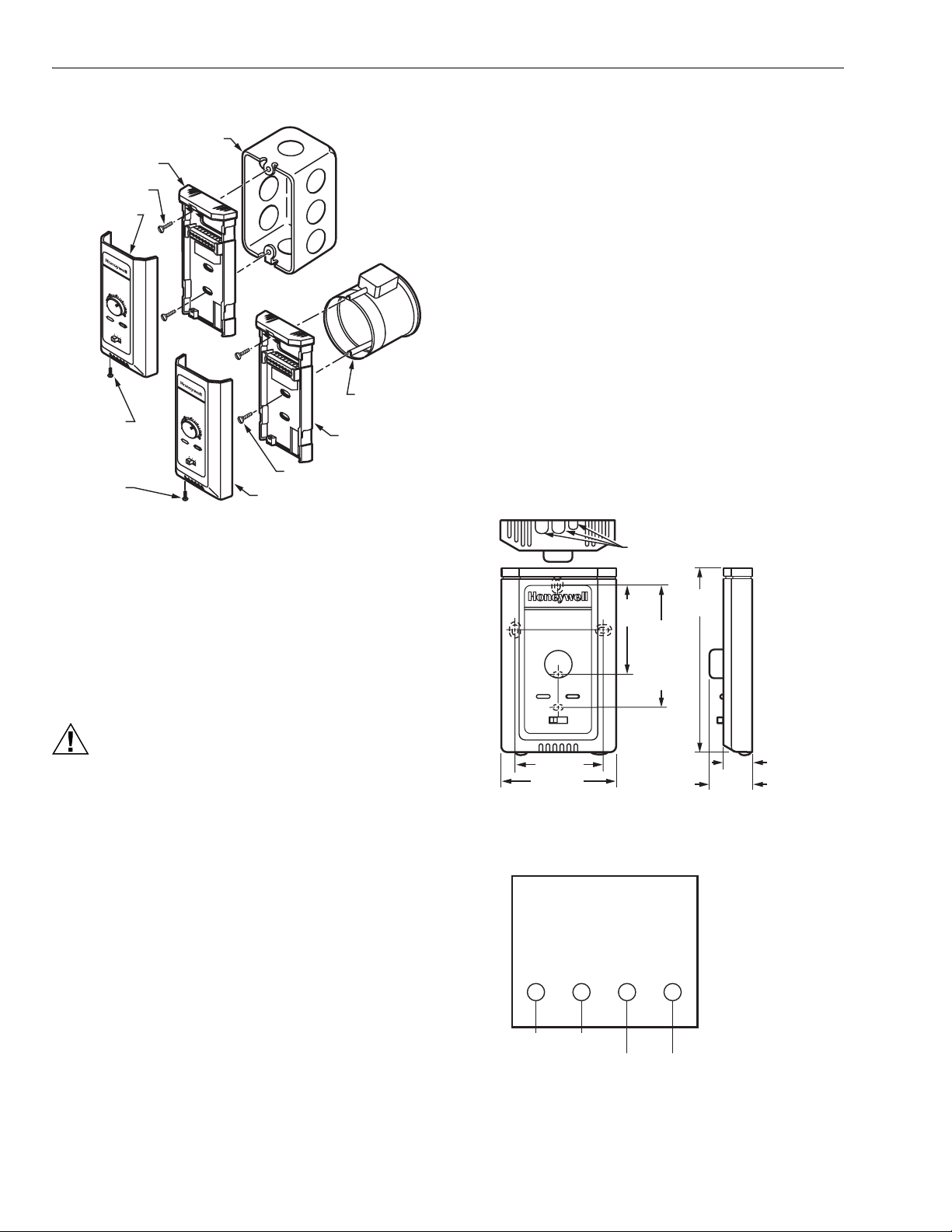
The wall modules can be mounted on a wall, on a standard
utility conduit box using No. 6 (3.5 mm) screws or on a 60 mm
wall outlet box (see Fig. 3). When mounting directly on a wall,
use the type of screws appropriate for the wall material.
M11394
T7770E
BUTTON HEAD
SOCKET CAP
SCREW
ALLEN TOOL
STEP 1
STEP 2
STEP 3
70
65
60
55
75
auto 0 1
80
85
M17988
PRESS SHADED AREA
OF TAB WITH THUMB TO
RELEASE TERMINAL BLOCK
FOR EASIER WIRING
T7770A,B,C,D,E,F,G WALL MODULES
95-7538—4 2
Fig. 3. Mounting wall modules on standard utility
conduit box or 60 mm wall outlet box.
See Fig. 4 for subbase mounting dimensions.
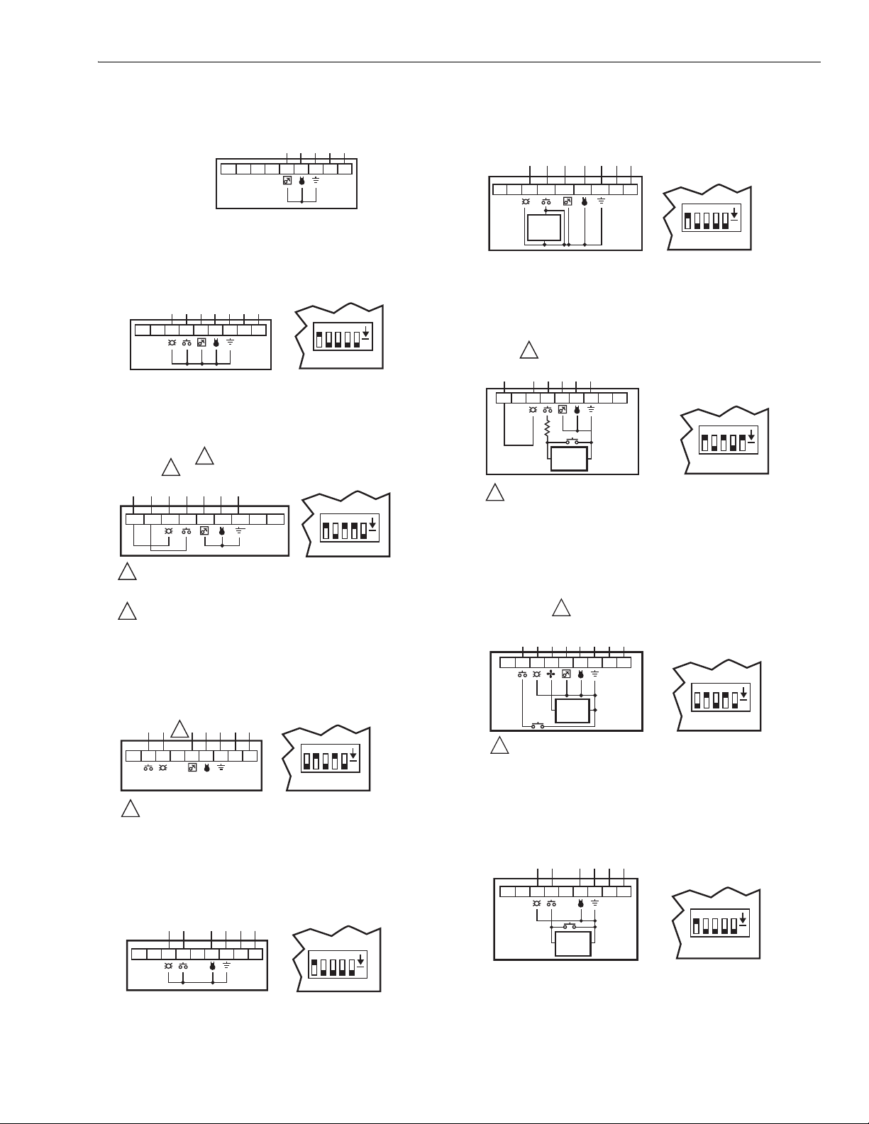
Wiring
Attach the wires from the device sensor terminals to the
appropriate wall module terminals. See Fig. 5 through 16.
NOTE: None of these wall modules are compatible with
W7751A,C,E,G Controllers.
CAUTION
Improper Electrical Contact Hazard.
Screw type terminal blocks are designed to accept
no more than one 14 AWG (2.5 sq mm) conductor.
Connect multiple wires that are 14 AWG (2.5 sq mm)
with a wire nut. Include a pigtail with this wire group
and attach the pigtail to the individual terminal block.
Wiring Modules Without a Removable Terminal Block
Attach the wires as follows:
1. Connect controller sensor leads to the sensor screw
terminals.
NOTE: T7770A1006 have a 20K ohm sensor,
T7770A3002 have a 10K ohm sensor. They
are for use in averaging for the T7350. They do
not have E-bus network terminals.
2. If the module has E-bus terminals, connect the
controller E-bus leads to these screw terminals.
NOTE: Wire the E-Bus using Level IV 22 AWG
(0.34 sq mm) plenum or non-plenum rated,
unshielded, twisted pair, solid conductor wire.
NOTE: Unless otherwise noted, sensor and E-Bus
terminals are not polarized; reversing the two sensor
leads does not affect the signal.
Wiring Modules With a Removable Terminal Block
Wire the terminal blocks as follows:
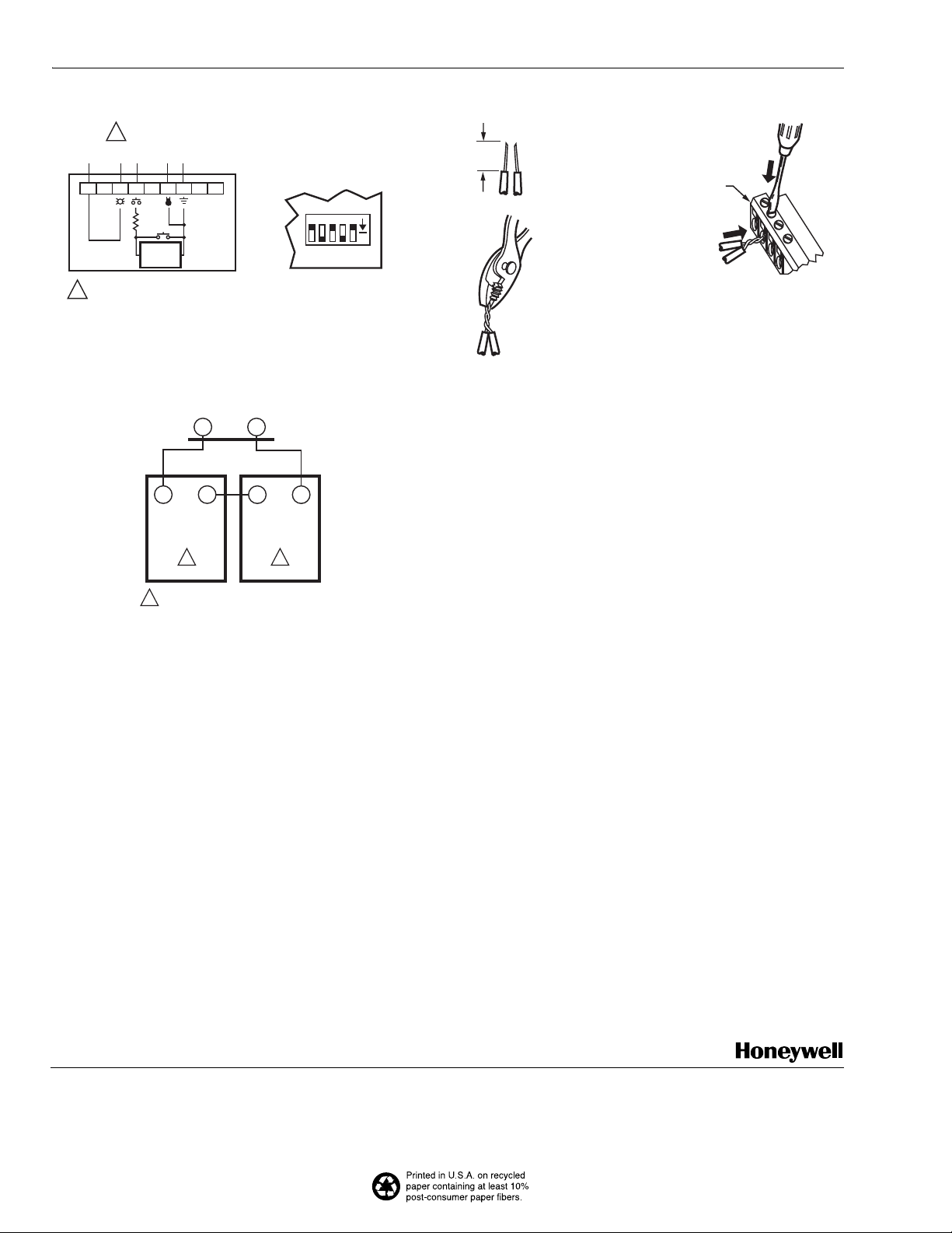
1. For single wires, strip 3/16 in. (5 mm); for multiple wires
going into one terminal, strip 1/2 in. (13 mm) insulation
from the conductor.
2. If two or more wires are being inserted into one
terminal, twist the wires together before inserting.
NOTE: When two or more wires are being inserted
into one terminal, be sure to twist them
together. Deviation from this rule can result
in improper electrical contact. See Fig. 17.
3. Insert the wire in the required terminal location and
tighten the screw to complete the termination.
4. Verify wall module wiring with Fig. 5 through 16.
NOTE: Wire the E-Bus using Level IV 22 AWG (0.34 sq mm)
plenum or non-plenum rated, unshielded, twisted
pair, solid conductor wire.
Fig. 4. T7770A,B,C,D,E,F,G Subbase
dimensions in in. (mm).
Fig. 5. Wiring diagram for T7770A20XX Wall Modules.
M17989
STANDARD UTILITY
CONDUIT BOX
SUBBASE
NO. 6 SCREW
60 mm WALL
OUTLET BOX
SUBBASE
3.5 mm SCREW
FRONT COVER
BUTTON
HEAD
SOCKET
CAP SCREW
BUTTON
HEAD
SOCKET
CAP SCREW
70
65
60
55
75
auto 01
80
85
FRONT COVER
70
65
60
55
75
auto 0 1
80
85
15/16
(23)
M17990
3-3/16 (80) 1-1/4 (32)
5-1/16
(128)
KNOCKOUTS FOR
EUROPEAN APPLICATIONS
2-3/8 (60)
2-3/8
(60)
STANDARD
UTILITY
CONDUIT
BOX (2 X 4)
MOUNTING
HOLES
SENSOR SENSOR E-BUS E-BUS
SENSOR
SENSOR
NETWORK
BUS
NETWORK
BUS
M20359
E-BUS TERMINALS
ARE NOT USED FOR
C-BUS DEVICES.
T7770A,B,C,D,E,F,G WALL MODULES
3 95-7538—4
Fig. 6. Wiring diagram for T7770B10XX Wall Modules.
Fig. 7. Wiring diagram for T7770C10XX Wall Modules
wired to Excel 10 W7750, W7751, W7752.
Fig. 8. Wiring diagram for T7770C10XX, D10XX
Wall Modules wired to Excel 600/500/100/80/20.
Fig. 9. Wiring diagram for T7770C10XX, D10XX
Wall Modules wired to Excel 10 W7753.
Fig. 10. Wiring diagram for T7770D10XX Wall Modules
wired to Excel 10 W7750, W7751, W7752.
Fig. 11. Wiring diagram for T7770E10XX, F10XX
Wall Modules wired to Excel 10 W7752.
Fig. 12. Wiring diagram for T7770E10XX, F10XX
Wall Modules wired to Excel 600/500/100/80/20.
Fig. 13. Wiring diagram for T7770E10XX, F10XX,
G10XX Wall Modules wired to Excel 10 W7753.
Fig. 14. Wiring diagram for T7770G10XX Wall
Modules wired to Excel 10 W7752.
123456789
SENSOR
AI COM
(OR) GND
E-BUS
E-BUS
M11400
SETPT
E-BUS TERMINALS
ARE NOT USED FOR
C-BUS DEVICES.
M11401
BYPASS
LED
12345
ON
S4
PRINTED WIRING BOARD
DIP SWITCH POSITIONS
(S4-1,2,3,4=ON; 5=OFF)
123456789
SENSOR
AI COM
(OR) GND
E-BUS
E-BUS
SETPT
123456789
SENSOR
AI COM
M11402
SETPT
12345
ON
S4
LED
RETURN
BYPASS
RETURN
BYPASS
LED
1
2
1
2
USING AN EXCEL 20 WITH THIS WALLMODULE REQUIRES WIRING (AT
CONTROLLER) THE 1500 OHM BAG ASSEMBLY RESISTOR IN SERIES
WITH TERMINAL 7.
TERMINAL 5 IS USED ONLY WITH T7770C MODEL SENSORS.
NOTE: CHANGE AND VERIFY
DIP SWITCH POSITIONS FOR
THESE EXCEL CONTROLLERS
(S4-1,4=ON; 2,3,5=OFF)
123456789
SENSOR
GND
E-BUS
E-BUS
NOTE: VERIFY DIP
SWITCH POSITIONS
(S4-1,3,5=ON; 2,4=OFF)
M11403
SETPT
12345
ON
S4
BYPASS
LED
1
1
TERMINAL 5 IS USED ONLY WITH T7770C MODEL SENSORS.
123456789
SENSOR
GND
E-BUS
E-BUS
NOTE: VERIFY DIP
SWITCH POSITIONS
(S4-1,2,3,4=ON; 5=OFF)
M11404
12345
ON
S4
BYPASS
LED
SENSOR
GND
E-BUS
E-BUS
NOTES:
—T7770E HAS A SINGLE-SPEED FAN
—T7770F HAS A THREE-SPEED FAN
—VERIFY DIP SWITCH POSITIONS
(S4-1,2,3,4=ON; 5=OFF)
M11407
SETPT
12345
ON
S4
BYPASS/FAN
LED
FAN
SPEED
SWITCH
123456789
123456789
SENSOR
AI COM
NOTES:
—T7770E HAS A SINGLE-SPEED FAN
—T7770F HAS A THREE-SPEED FAN
—CHANGE AND VERIFY DIP SWITCH
POSITIONS FOR THESE EXCEL
CONTROLLERS (S4-2,4=ON;
1,3,5=OFF)
M11408
SETPT
BYPASS/FAN
LED
LED
RETURN
FAN
SPEED
SWITCH
1
1
USING AN EXCEL 20 WITH THIS WALL MODULE REQUIRES WIRING (AT
CONTROLLER) THE 1500 OHMBAG ASSEMBLY RESISTOR IN SERIES
WITH TERMINAL 7.
12345
ON
S4
123456789
SENSOR
GND
E-BUS
E-BUS
NOTE:
—T7770E HAS A SINGLE-SPEED FAN
—T7770F HAS A THREE-SPEED FAN
—VERIFY DIP SWITCH POSITIONS
(S4-1,3,5=ON; 2,4=OFF)
M11409
SETPT
12345
ON
S4
FAN
BYPASS
LED
FAN
SPEED
SWITCH
1
1 TERMINAL 5 IS USED ONLY WITH T7770E,F MODEL SENSORS.
123456789
SENSOR
GND
E-BUS
E-BUS
NOTES:
—T7770G HAS A THREE-SPEED FAN
—VERIFY DIP SWITCH POSITIONS
(S4-1,2,3,4=ON; 5=OFF)
M11410
12345
ON
S4
BYPASS
/
FAN
LED
FAN
SPEED
SWITCH
Automation and Control Solutions ACS Control Products
Honeywell International Inc. Honeywell Limited-Honeywell Limitée Honeywell AG
1985 Douglas Drive North 35 Dynamic Drive Böblinger Straße 17
Golden Valley, MN 55422 Scarborough, Ontario D-71101 Schönaich
M1V 4Z9 Phone (49-7041) 637-01
Fax (49-7041) 637-493
95-7538—4 B.B. Rev. 7-04 www.honeywell.com
T7770A,B,C,D,E,F,G WALL MODULES
Fig. 15. Wiring diagram for T7770G10XX Wall
Modules wired to Excel 600/500/100/80/20.
Fig. 16. Two T7770A3002 Wall Modules wired to a T7350
for temperature averaging.
Fig. 17. Attaching two wires at wall module terminals.
When all wiring is complete, attach the cover of the
T7770A,B,C,D,E,F,G Wall Module by reversing step 3
of Fig. 1. Insert and tighten locking screw by reversing
step 1 on Fig. 1.
NOTE: The locking screw must be installed and tight for
a secure T7770 installation.
123456789
SENSOR
AI COM
NOTES:
—T7770G HAS A THREE-SPEED FAN
—CHANGE AND VERIFY DIP SWITCH
POSITIONS FOR THESE EXCEL
CONTROLLERS (S4-2,4=ON;
1,3,5=OFF)
M11411
12345
ON
S4
BYPASS/
FAN
LED
LED
RETURN
FAN
SPEED
SWITCH
1
1
USING AN EXCEL 20 WITH THIS WALL MODULE REQUIRES WIRING
(AT CONTROLLER) THE 1500 OHM BAG ASSEMBLY RESISTOR IN SERIES
WITH TERMINAL 7.
M22408
T4 T3
T7350 SUBBASE
T7770A3002
T4 T3
T7770A3002
T4 T3
1
11
THE T7771A3002 IS A 10K OHM SENSOR.
1/2
(13)
STRIP 1/2 IN.
(13 MM) FROM
WIRES TO BE
ATTACHED AT
ONE TERMINAL.
1.
2.
TWIST WIRES
TOGETHER
WITH PLIERS
(A MINIMUM OF
THREE TURNS).
3.
CUT TWISTED END OF WIRES TO
3/16 IN. (5 MM) BEFORE INSERTING
INTO TERMINAL AND TIGHTENING
SCREW. THEN PULL ON EACH WIRE
IN ALL TERMINALS TO CHECK FOR
GOOD MECHANICAL CONNECTION.
M11413
CONTROLLER OR
WALL MODULE
E-BUS CONNECTOR
TERMINALS
Questo manuale è adatto per i seguenti modelli
6
Indice
Altri manuali Honeywell Rack e supporto

Honeywell
Honeywell 013046 Manuale utente

Honeywell
Honeywell Sensepoint XCD Manuale utente

Honeywell
Honeywell 7800 SERIES Manuale utente

Honeywell
Honeywell 5815RMK Manuale tecnico

Honeywell
Honeywell 50024917-002/U Manuale utente

Honeywell
Honeywell SK-NIC-KIT Manuale tecnico

Honeywell
Honeywell CT40-SH-DC Manuale utente

Honeywell
Honeywell CN85-WL-6DESK Manuale utente

Honeywell
Honeywell CT40-WS-PB Manuale utente

Honeywell
Honeywell HMM12 Manuale utente


