HydraMaster CTS 450 Manuale utente

CTS 450 Hot Carbonating
Truckmount System™
Manufactured Exclusively for
By
Mukilteo, Washington
Machine Serial Number _______________
Copyright © 2012
HydraMaster Corporation
No Part of this manual may be reproduced or used in any form or by any means (i.e. graphic,
electronic, photocopying or electronic retrieval systems) without written permission by
HydraMaster© Corporation. All Rights Reserved.
Revised March 23, 2012


Table of Contents
Table of Contents
List of Figures
Quick Reference
GENERAL INFORMATION..........................................................................Section 1
Telephone Numbers...........................................................................1-2
Precautions........................................................................................1-3
Responsibilities..................................................................................1-6
Vehicle Preparation............................................................................1-8
High Altitude Operation Preparation..................................................1-12
Local Water Precautions....................................................................1-13
Hard Water Advisory...............................................................1-13
Hard Water Area Map............................................................. 1-13
Water Softener........................................................................1-13
Waste Water DisposalAdvisory..............................................1-14
MACHINE SPECIFICATIONS......................................................................Section 2
Machine Layout (Gas) ....................................................................... 2-3
Machine Layout (Diesel)....................................................................2-4
Component Descriptions ................................................................... 2-5

HydraMaster Corporation
CTS 450 Owner’s Manual
CTS 450Hot Carbonating Truckmount System
OPERATING INSTRUCTIONS .................................................................... Section 3
Start Up (Gas and Diesel Versions)...................................................3-1
Carpet or Upholstery..........................................................................3-2
Flood Extraction.................................................................................3-2
Solution Fill Procedure.......................................................................3-3
Shut Down.........................................................................................3-3
Safety Shutdown................................................................................3-4
General Operating Information..........................................................3-4
MACHINE MAINTENANCE.........................................................................Section 4
Engine................................................................................................4-1
Air Filter .............................................................................................4-1
Engine Oil and Filter Change.............................................................4-2
Engine Coolant..................................................................................4-3
Spark Plug Replacement (Gas Engine Only) .................................... 4-3
Fuel Filter (Gas Only) ........................................................................ 4-4
Fuel Separator (Diesel Engine) ......................................................... 4-4
Blower................................................................................................4-5
Blower Oil Change.............................................................................4-5
Recovery Tank...................................................................................4-6
Solution System.................................................................................4-8
OriceManifold..................................................................................4-8
General Maintenance ........................................................................ 4-9
Freeze Guard Information..................................................................4-9
Maintenance Logs

CTS 450 Owner’s Manual
Hot Carbonating Truckmount System CTS 450
MACHINE ASSEMBLIES AND PARTS LIST..............................................Section 5
WATER AND CHEMICAL SYSTEM ............................................................ Section 6
ELECTRICAL SYSTEM...............................................................................Section 7
WARRANTY INFORMATION.......................................................................Section 8
Limited Warranty Plan .......................................................................8-2

HydraMaster Corporation
CTS 450 Owner’s Manual
CTS 450Hot Carbonating Truckmount System
Fig. 1-1 Plywood Installation..............................................................1-8
Fig. 1-2 Astroturf and Roof Vent Installation...................................... 1-8
Fig. 1-3 Recommended Placement ..................................................1-9
Fig. 1-4 Installation Using Tie-down Cleats........................................ 1-10
Fig. 1-5 Hard Water Map....................................................................1-15
Figures2-1through2-6arephotosrelatingtomachinespecications
Figures 3-1 through 3-4 are photos relating to operating instructions
Figures 4-1 through 4-15 are photos relating to machine maintenance
Machine Assemblies and Parts Lists ................................................. 5-1
Fig. 5-1 Machine Assembly - Front View ........................................... 5-1
Fig. 5-2 Machine Assembly - Rear View............................................ 5-2
Fig. 5-3 Machine Assembly - Side View.............................................5-3
Fig. 5-4 Frame Assembly................................................................... 5-5
Fig. 5-5 Dash Assembly - Front View.................................................5-7
Fig. 5-6 Dash Assembly - Rear View ................................................. 5-8
Fig. 5-7 Brow Assembly - Front View................................................. 5-10
Fig. 5-8 Brow Assembly - Rear View.................................................. 5-11
Fig. 5-9 Compressor Regulator Assembly ......................................... 5-13
Fig. 5-10 Engine Assembly - Right View.............................................. 5-15
Fig. 5-11 Engine Assembly - Left View ................................................5-16
Fig. 5-12 Exhaust Assembly.................................................................5-20
List of Figures and Tables

CTS 450 Owner’s Manual
Hot Carbonating Truckmount System CTS 450
Fig. 5-13 Air Cleaner Assembly............................................................ 5-20
Fig. 5-14 Air Compessor Assembly ....................................................... 5-21
Fig. 5-15 Compressor Check Valve Assembly ......................................5-25
Fig. 5-16 Blower Assembly - CTS 450 Gas.......................................... 5-26
Fig. 5-17 Dump & Vacuum Bracket Assembly - Front.......................... 5-28
Fig. 5-18 Dump & Vacuum Bracket Assembly - Rear .......................... 5-29
Fig. 5-19 Coolant Heat Exchanger Assembly ...................................... 5-31
Fig. 5-20 Blower Exhaust Heat Exchanger Assembly..........................5-33
Fig. 5-21 15 Gallon Chemical Jugs Assembly ..................................... 5-35
Fig. 5-22 15 Gallon Chemical TankAssembly...................................... 5-37
Fig. 5-23 100 Gallon Universal Recovery TankAssembly ................... 5-38
Fig. 5-24 100 Gallon Universal Recovery Tank CoverAssembly......... 5-41
Fig. 5-25 Vacuum Relief Valve Assembly............................................. 5-42
CTS 450 Diesel
Fig. 5-26 Machine Assembly - Front View (CTS 450 Diesel)............... 5-44
Fig. 5-27 Machine Assembly - Rear View (CTS 450 Diesel)................ 5-45
Fig. 5-28 Machine Assembly - Side View (CTS 450 Diesel)................ 5-46
Fig. 5-29 Dash Assembly - Front View (CTS 450 Diesel).................... 5-48
Fig. 5-30 Dash Assembly - Rear View (CTS 450 Diesel)..................... 5-49
Fig. 5-31 Brow Assembly (CTS 450 Diesel).........................................5-52
Fig. 5-32 Frame Assembly (CTS 450 Diesel)....................................... 5-54
Fig. 5-33 Engine Assembly - Right View (CTS 450 Diesel) ................. 5-56
Fig. 5-34 Engine Assembly - Left View (CTS 450 Diesel).................... 5-57
Fig. 5-35 Air Cleaner Assembly (CTS 450 Diesel)............................... 5-61
Fig. 5-36 Blower Assembly (CTS 450 Diesel)...................................... 5-62

HydraMaster Corporation
CTS 450 Owner’s Manual
CTS 450Hot Carbonating Truckmount System
Fig. 6-1 Solution Flow Diagram.............................................................6-1
Fig. 7-1 Wiring Diagram CTS 450 Gas (Sheet 2)..................................7-1
Fig. 7-2 Wiring Diagram CTS 450 Gas (Sheet 3)..................................7-2
Fig. 7-3 Wiring Diagram CTS 450 Gas (Sheet 4)..................................7-3
Fig. 7-4 Wiring Diagram CTS 450 Diesel (Sheet 1) ..............................7-4
Fig. 7-5 Wiring Diagram CTS 450 Diesel (Sheet 2) ..............................7-5
Fig. 7-6 Wiring Diagram CTS 450 Diesel (Sheet 3) ..............................7-6
Fig. 7-7 Electrical Schematic CTS 450.................................................. 7-7
CTS 450 Owner’s Manual
Hot Carbonating Truckmount System CTS 450
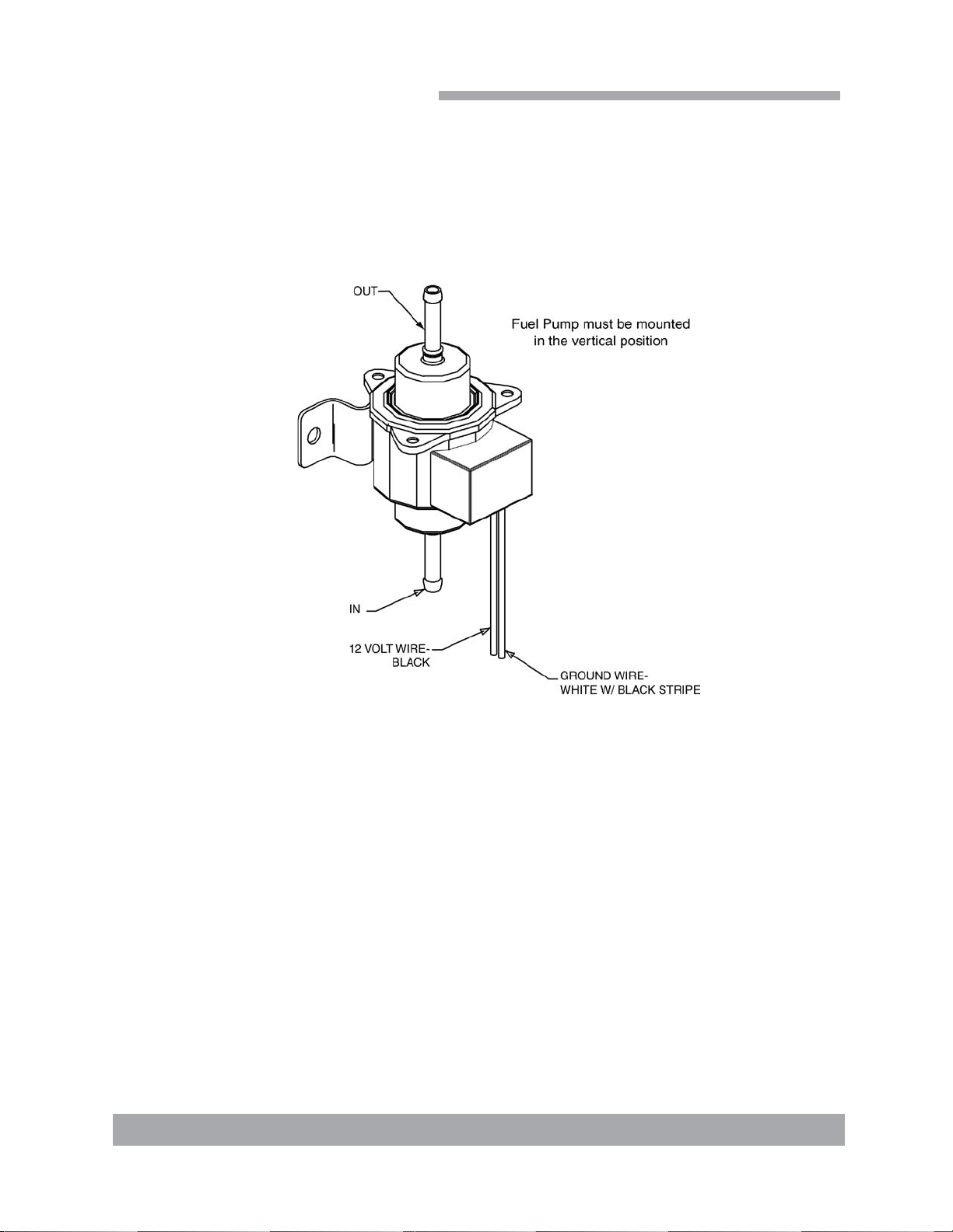
Fuel Pump Assembly
B-4627 Rev-
Quick Reference

Page 1-1 : CTS 450 Owner’s Manual
CTS 450 Hot Carbonating Truckmount System
This manual contains installation and operation instructions as well as information
required for proper maintenance, adjustment and repair of this unit. Since the first and
most important part of repair work is the correct diagnosis of the problem, component
manual troubleshooting charts have been included for your convenience.
Unlike a garden tractor, lawn mower or cement mixer, all having one or two functions to
perform, the truckmounted carpet cleaning plant has many functions to perform simulta-
neously.
• The engine has to run at a consistent rpm.
• The vacuum has to pull air and dirty water back from cleaning site.
• The solution system provides stable pressure at proper water flow for cleaning.
• The heating system must maintain proper heat.
• The vacuum tank must store dirty water until drained.
As you can see, this machine is not just a simple turn-key operation where your only worry
is “Does it start?”
General Information
Indice
Altri manuali HydraMaster Sistema idrico


Manuali Sistema idrico popolari di altre marche

Spirotech
Spirotech SPIROVENT SUPERIOR S250 Manuale utente

Culligan
Culligan Aqua-Cleer Aqua-Cleer Advanced Drinking Water... Manuale utente

A.O. Smith
A.O. Smith Dura-Max AJH - 1000A - P Manuale utente

Microline
Microline T.F.C.-4 Manuale

Eureka Forbes
Eureka Forbes Aquaguard Select Manuale utente

Cetetherm
Cetetherm AquaEfficiency Manuale utente


