Hydro WQM-100 Manuale utente

WQM-100
Water Quality Monitor
Instruction Manual
WQM-100 Rev. 8/25/2020
The information contained in this manual was current at the time of printing. The most current
versions of all Hydro Instruments manuals can be found on our website: www.hydroinstruments.com
1

Hydro Instruments
WQM-100 Water Quality Monitor
Table of Contents
I. General Information .................................................................................3
1. Important Operational Information
2. Important Handling Considerations
3. Electrode Lifespan
II. Installation ................................................................................................4
1. Sample Water Connection and Control
2. Sample Water Disposal Considerations
3. Sample Point Selection
4. Mounting the Electrodes
5. Wiring the Electrodes
6. Installation Inspection
III. Calibration and Programming .................................................................8
1. Conditioning
2. Programming the WQM-100
3. Programming Access
3. Operating the Keypad
IV. Explanation of Operation Mode Screens .............................................11
V. Explanation of Confi guration Mode Screens ......................................14
VI. Explanation of PID Control Mode Screens ..........................................18
VII. Maintenance & Cleaning ........................................................................20
1. Inlet Filter Screen
2. Flushing the Measurement Cell
3. Thermistor
4. pH Electrode
5. ORP Electrode
6. Conductivity Electrode
VIII. Troubleshooting .....................................................................................21
IX. Optional Data Logger .............................................................................24
Figures:
1. Sample Water Piping Examples ......................................................................5
2. Sample Point Sources .....................................................................................6
3. Installation Example ........................................................................................6
4. Example Mounting Gland, Quick-Disconnect Cap & Cable Assembly ............7
5. Operation Menu Flow Chart ............................................................................9
6. Hidden Confi guration & Live Data .................................................................10
7A. Confi guration Menus .....................................................................................12
7B. Confi guration Menus .....................................................................................13
8. Circuit Boards ................................................................................................27
9. Monitor Internal Wiring and Connections ......................................................28
Drawings:
Electrode Measurement Cell .........................................................................26
2

I. GENERAL INFORMATION
1. Important Operational Information
To increase the life expectancy, accuracy and response of the electrode adhere to the following
operational guidelines:
1. Keep the electrode wet. Allowing the electrode to dry out will lead to slow response, erroneous
readings and damage.
2. Clean the electrode regularly
• Take care when cleaning the electrode. Never use a brush or coarse surface for cleaning.
• To clean, simply rinse the electrode with water. Blot (do not rub) with a lint-free paper towel to
remove excess moisture.
• Specially formulated cleaning solutions can be used to clean the electrode too.
• Wiping the glass can produce a static charge which interferes with the electrodes ability to
read.
2. Important Handling Considerations
The electrodes are shipped in a cap containing a solution. The electrode should only be removed from
this solution when it is ready to be installed and used.
NOTE: If the electrode will be subject to infrequent use it should be stored in Storage Solution or in a
pH 4 buffer solution if Storage Solution is not available. Do not store the electrode in deionized (DI)
water as this will damage the electrode.
3. Electrode Lifespan
Just like any piece of equipment, electrodes need to be replaced from time to time as regular
maintenance. As sensors age they become less responsive. The off set and slope are metrics
by which to measure the electrodes functionality. Refer to Appendix A in this document for more
information.
The manufacturing lot number can be found on the label on the electrode. This information can be
used to determine the age of the electrode.
3

II. INSTALLATION
Refer to Figure 3 for this section.
1. Sample Water Connection and Control: The following are some considerations relating to the
sample water supply. The WQM-100 Water Quality Monitor requires a constant supply of sample water
at a controlled rate and pressure. Precautions should also be taken to ensure that the sample water
reaching the measurement cell is not altered as it passes through the sample water piping. Also, the
connection to the sample point should be made in such a way to avoid receiving air or sediment from
the pipe. Consider fi gure 4 when creating your sample water line
Flow: The sample water fl ow rate should be controlled at an ideal rate of 500 ml/minute (8 GPH).
A fl ow meter and rate control valve may be necessary to achieve and maintain this fl ow rate. This
can be installed upstream from the measurement cell.
Pressure: Where the sample point has a water pressure higher than 87 PSI (6 bar), a pressure-
reducing valve must be employed to deliver the sample water to the measurement cell. The sample
water entering the measurement cell should be at a pressure below 87 PSI (6 bar). If the sample
point pressure is too low, then it may be necessary to use a sample pump to deliver the sample water
to the measurement cell.
Other Considerations: It should be considered, that any biological growth inside the sample piping
system will have some adverse eff ects. This can cause the sample water reaching the measurement
cell to not be an accurate sample. For example, the ORP could change as the sample water passes
through the sample water piping system. For this reason, it may be necessary to periodically clean
the sample water piping system to prevent any biological growth or clear out residual chemical
buildup. Also, it is generally not recommended to use a fi lter in this piping system because as the fi lter
collects particles it can lead to inaccurate readings. However, in certain installations with signifi cant
amounts of solids in the sample water (particularly iron and manganese) the use of sample water
fi lters may be necessary.
2. Sample Water Disposal Considerations: If no reagent and/or pH buff er chemical is being
injected, then the disposal of the water departing the measurement cell is usually not a signifi cant
concern. However, if some reagent and/or pH buff er chemicals are being injected, then all applicable
regulations should be considered before making the decision of how and where to dispose of
the wastewater exiting the measurement cell. Refer to the MSDS of the chemical in question for
instructions on proper disposal.
3. Sample Point Selection:
There are at least two general concepts to consider when selecting the sample point location. First,
is to select a point that allows reliable determination of the parameter to be measured at the most
critical point for the particular installation. Second, is to take into consideration any chemical injection
control timing. A balance between these considerations must be reached.
Each system is unique, however in general the goal of the chemical injection is to achieve some result
by maintaining a certain measurement at a particular point in the system. For example, to maintain
a specifi c chlorine residual at the exit of the drinking water facility. The location should be selected
so that the injected chemical is already fully mixed so that an accurate sample can be sent to the
measurement cell.
WARNING! Do not run the instrument without sample water running through it. Lack
of, or interruption of water fl ow can cause premature failure of the electrodes.
4

To drain
127(6DPSOHSUHVVXUHHQWHULQJ
WKHDQDO\]HUPXVWEHUHGXFHGWR
36,%DURUOHVV
Grab sample
valve
6DPSOHZDWHU
IORZPHWHU
3UHVVXUH
UHGXFLQJYDOYH
3UHVVXUH
UHGXFLQJYDOYH
Low pressure
sample water
source
<VWDLQHU
6DPSOH
SXPS
Pressurized
sample water
source
Examples for typical sample water sources
FIGURE 1 (Sample Water Piping Examples)
It should also be considered that the sample point should be located such that the residual reading
can be used as a control signal for the chemical injection. Especially, it should be considered that if
there is a long time delay between chemical injection changes and the change being detected by the
measurement cell, then chemical injection control is adversely aff ected. The delay time should be
kept as short as possible. We recommend that the time be less than 5 minutes.
5

!IR
3EDIMENT
!IR
3EDIMENT
!IR
3EDIMENT
!IR
3EDIMENT
0//2 0//2
'//$ "%34
FIGURE 2 (Sample Point Sources)
FIGURE 3 (Installation Example)
TRUE
BLUE
TRUE
BLUE
TRUE
BLUE
0LQ ['LDpipe
,GHDO ['LDpipe
S+RU2536LJQDOP$:DWHU)ORZ6LJQDOP$
NET #1 = 1234
NET #2 = 5678
:DWHU4XDOLW\0RQLWRU
WQM-100
:DOO3DQHO2PQL9DOYH
9DFXXP5HJXODWRU
(MHFWRU
6DPSOH:DWHU359
RAH-PRV (optional)
&RUSRUDWLRQ6WRS
9HQW
To Drain
6

4. Mounting the Electrodes: If applicable, install the necessary hardware to mount the electrode. This
may be a separate acrylic pot or a PVC gland that threads into the fl ow cell.
1. Remove the electrode from its buff er cap and place it into its mounting gland. Secure it into place
by gently threading it into the gland, rotating clockwise until it stop.
2. Connect the quick-disconnect cap & cable assembly to the top of the pH or ORP electrode by
gently threading the cap on, rotating clockwise until it stops.
5. Wiring the Electrodes: The WQM-100 will have its electrode connections pre-wired and only the
electrode(s) need to be connected. If an electrode is being added that the unit was not originally
supplied with or if the cable assembly is being replaced, please referece the following installation
points.
NOTE: If installing an electrode that the equipment was not supplied with, it may be necessary to
add an additional liquid tight cable grip into the controller enclosure. This hardware will have been
provided with the new electrode that is to be installed.
1. With the instrument powered off , run the cable portion of the electrodes quick-disconnect cap &
cable assembly through the liquid tight cable grip in the controllers enclosure.
2. Refer the circuit board fi gure (FIgure 8) for wiring connection terminals for the electrode that is
being connected.
6. Installation Inspection: Reference the troubleshooting table in this document if needed.
• Make sure that the sensing glass is fully submerged.
• Make sure that the sensing glass is free of air bubbles.
• There should be a reading on the instrument display.
FIGURE 4 (Mounting Gland, Quick-Disconnect Cap & Cable)
WARNING! Electrical hazards are involved with this installation. Only qualifi ed personnel
should perform this installation.
7

III. CALIBRATION AND PROGRAMMING
1. Conditioning: Before calibration is carried out, the water quality monitor must be operated for
several hours to allow the readings to stabilize.
a. Start the sample water fl ow to the measurement cell(s).
c. An ideal fl ow rate of 500 ml/minute (8 GPH) should be provided. Under all circumstances, the
electrodes must be kept wet, even if the sample water fl ow stops periodically. Maximum sample
water pressure is 5 psig. See Figure 1.
d. Turn on the power to the monitor.
e. Check for air bubbles in the sample line and measurement cell(s). Remove any air bubbles.
f. Allow the equipment to operate with the sample water fl owing for several hours. After this, the
electrode(s) can be calibrated.
2. Programming the WQM-100 Water Quality Monitor
a. Operation (See Section VII): This is the normal operation state of the WQM-100. It provides
a display of the current readings; Temperature, (optional) pH, (optional) ORP, (optional)
Conductivity, Live Charts and any alarm conditions that may exist.
b. Configuration and Calibration (Programming) (See Section VIII): These screens are used to
set up the display options, operational parameters and other features.
c. PID Control (See Section IX): These parameters confi gure the PID Control program in the
software. These parameters perform proportional, set-point or compound loop control. One or
more of the analog outputs (AO1 through AO4) can be programmed to transmit a 4-20 mA control
signal.
3. Programming Access
a. Operation Mode: This is the standard operatonal state during initial powering of the device. To
return to this mode from any other screen simply press the button repeatedly.
b. Configuration and Calibration: This is accessed from the Operation screen by pressing the
button until the password screen is reached. Then enter the password “100” and then press the
button.
c. PID Control: These parameters will display several general status and control screens in the
Operation Mode. Access to the screens which allow this program to be set-up are listed among
the other operational parameters in the Confi guration menus. Press the button (in the
Operation Mode) until the password screen is reached. Then enter the password “100” and press
the button.
4. Operating the keypad
1. Navigation: To move from one screen to another, simply press the and buttons to reach
the desired screen. Navigation between screens is possible in either direction.
2. Adjustment of Displayed Parameters: To adjust a displayed parameter in the Confi guration
Mode, simply use the and buttons to increase or decrease. Once a parameter has been
set to the desired position, pressing either or button to leave the screen will cause the new
parameter to be stored. To select a blinking option (such as “Temperature Cal – Yes/No”), use the
arrow buttons as needed to make the desired selection blink then press the button.
8

FIGURE 5 (Operation Menu Flow Chart)
Enter Password
Begin I/O Hold?
Hold Time
Alarm Status
pH
ORP
Cond
Temp
ORP 620 mV
Temp 70F
(1 hr)
Ph 7.54
(1 hr)
(1 hr)
Cond 0.62 mS
(1 hr)
72 (17(5&21),*85$7,21 $)7(5
(17(5,1* 3$66:25'
0DLQ2SHUDWLRQ6FUHHQV /LYH&KDUWV 6WDWXV$FFHVV
%R[LQGLFDWHVVHOHFWHGLWHP
,QFUHDVHWRJJOHRUVHOHFWLWHP
'HFUHDVH
0RYHVFUHHQRUVHOHFWLRQER[
0RYHVFUHHQRUVHOHFWLRQER[
8VHU,QWHUIDFH
+LGGHQ
9
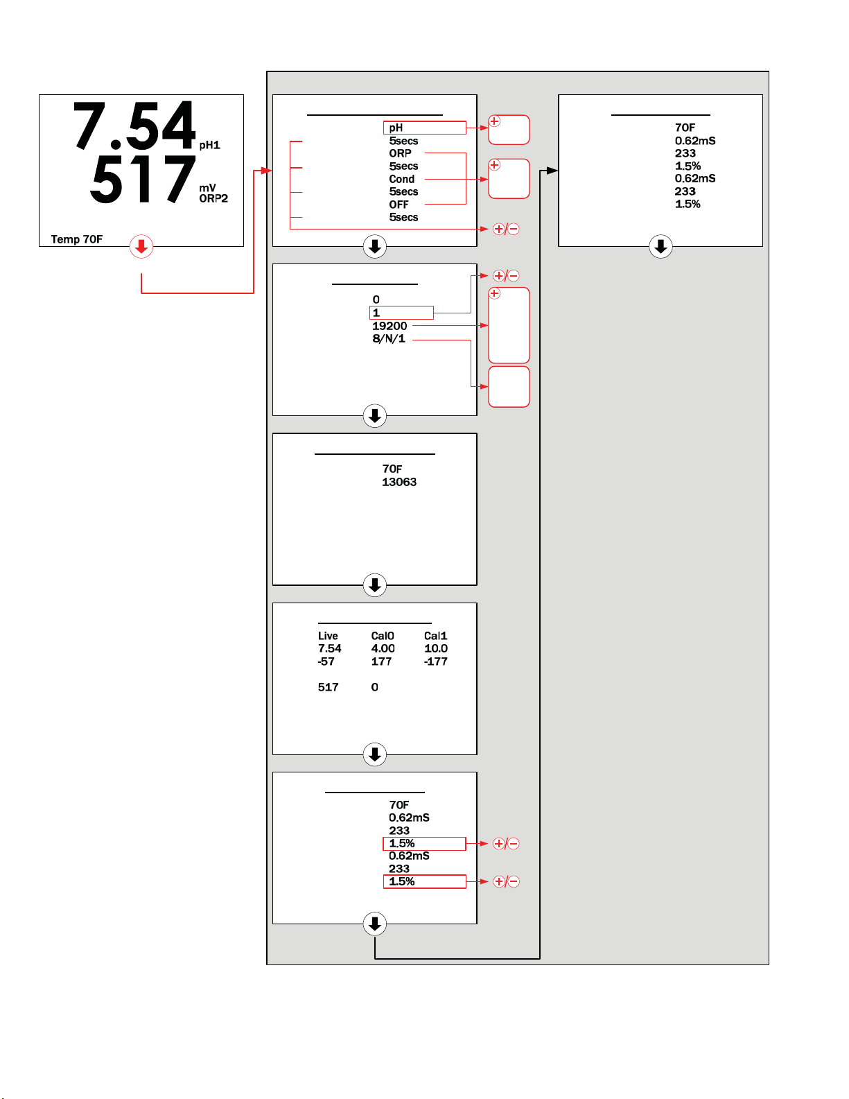
FIGURE 6 (Hidden Configuration & Live Data Screens)
Cond Live Data
Temp
Cond 3
ADC 3
TempCo 3
Cond 4
ADC 4
TempCo 4
Cond Live Data
Temp
Cond 1
ADC 1
TempCo 1
Cond 2
ADC 2
TempCo 2
pH/ORP Live Data
pH1
mV
ORP2
mV
Temp Sensors Live
Temp
Ohms
Probe Configuration
Probe 1
Filter Time
Probe 2
Filter Time
Probe 3
Filter Time
Probe 4
Filter Time
0DLQ2SHUDWLRQ6FUHHQ
Modbus Setup
Packet Count
Node Num
Baud Rate
Data Form
+LGGHQ&RQILJXUDWLRQ/LYH'DWD6FUHHQV
S+
253
&RQG
2))
1
1
(
2
+2/' )25 6(21'6%$&. 720$,123(5$7,216&5((1
S+
253
2))
10
Indice


