
Hydrofarm Autopilot PX2 Manuale utente

INSTRUCTIONS
APDPX2
PX2 ADVANCED LIGHTING CONTROLLER

Hydrofarm.com
2
The Autopilot PX2 Advanced Lighng Controller provides precision photoperiod control of
up to 512 xtures in two independently controlled zones, all from one centralized locaon.
Designed to work with any controllable Phantom or Core HID xtures, as well as PHOTOBIO
and Phantom LED xtures, the PX2 can control 512 digital HID xtures (256 per zone), or
25–100 analog LED xtures (depending on installaon dierences). The PX2 oers the exibility
to operate both zones analog or digital, or one zone analog and the other digital. With this
versale, dual-zone conguraon, growers can ...
• Optimize spectral treatments by checkerboarding lighting technologies within the same
environment (e.g., HPS with CMH, LED with CMH)
• Save power by checker boarding identical fixtures while reducing output to one of the zones
during the light cycle within the same environment
• Alternate rows and zones within the same environment
• Enhance uniformity by independent control over perimeter versus interior of the
environment
Powerful features, precise and independent controls
The PX2 provides independent control of the following features in each of its dual zones:
• Photoperiod timing to control light and dark cycles
• Photosynthetic photon flux control to precisely schedule the PPF being emitted from fixtures
during the light cycle (wattage or percentage)
• Auto-dimming when temperature exceeds set points
• Emergency auto-shutdown of lights upon user-defined over-temperature events
• Configurable restrike delay times to eliminate lamp-damaging hot starts
• Sunrise/sunset simulation settings to provide a gradual ramp-up and down at both ends of
your photoperiod
• Built-in battery backup
Two dedicated temperature sensors, one for each zone
These sensors provide real-me data for automated temperature-based dimming, as well as
a high temperature shutdown feature that protects your garden. The PX2 eliminates inrush
current and replaces tradional lighng contactors, reducing infrastructure investment.
Updated locking signal and data cables
All cables are shielded from electromagnec interference to ensure uncompromising signal
reliability and communicaon.
WHAT’S IN THE BOX
The Autopilot PX2 Advanced Lighting Controller (APDPX2) includes:
1 – Autopilot PX2 w/locking mini 3P IP65 female connectors 1 – 5' 100V–240V, 50/60 Hz
2 – 50' white temperature probes power adapter
2 – 20' locking mini 3P M-RJ 6P white RF shielded data cable
(for controllable Phantoms with a USB port)
2 – Mounng screws
2 – 20' locking mini 3P M-2P white RF shielded data cable
(for PHOTOBIO xtures with an LLT connector)
1 – Instrucons
SPECIFICATIONS
TECHNICAL PARAMETERS
Voltage HID 100–240V Qty of zones can be controlled Max 2
Frequency 50/60Hz Qty of HID xtures can be controlled Max 256 x 1 zone
Power source
for controller 5V/2A Qty of LED xtures can be controlled
Max 25–50 x 1
zone (depending
on driver)
OVERVIEW
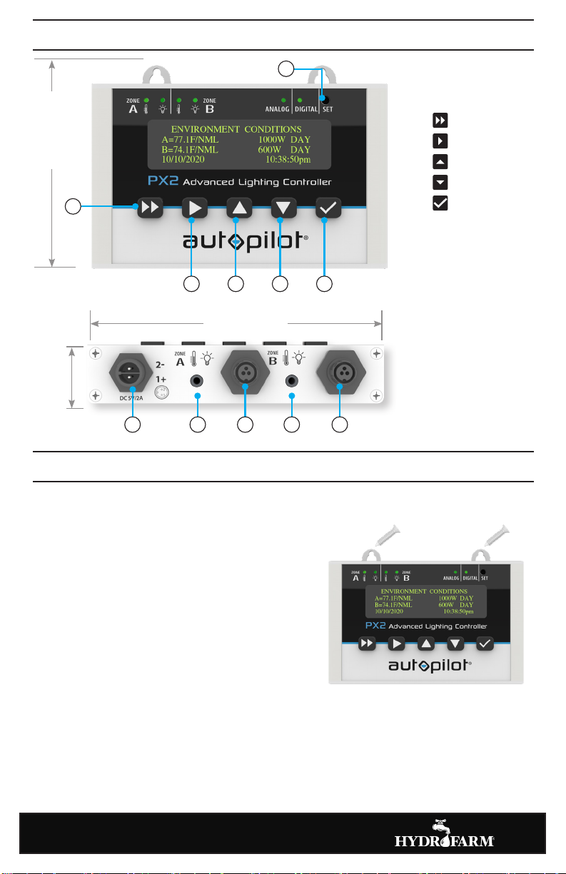
3
INSTALLING THE PX2
1. Securely wall mount the PX2 at eye level outside the
growing environment, using the provided screws
and mounng holes.
2. Plug the power adapter into an outlet and connect
the other end to the PX2 power supply port (A – see
image above). Ensure threaded connecon is ght.
3. Plug the temperature probes into the corresponding
ports (B, D) and run your probe cables their full
length up to and across the ceiling, toward the
center of the grow space. Suspend the probes above
the plant canopy. Take care not to stress or damage
the probe cables when securing them to walls and
ceilings.
4. Connect the zone signal cables (C, E).
IMPORTANT: A bare probe receiving direct light from a xture can cause premature dimming
and/or inaccurate temperature readings. When seng up the temperature probes, shield them
from exposure to direct light.
INSTALLATION
4" (99.8 mm)
1
3
2
456
1 SET buon
2 Turn the page
3 Cursor Right
4 Increase
5 Decrease
6 Menu/
Conrm/Save
APower supply port
BTemperature probe
port Zone A
CSignal port Zone A
DTemperature probe
port Zone B
ESignal port Zone B
OVERVIEW
Mounng holes
C EDB
A
1" (27.1 mm)
5" (127.5 mm)

Hydrofarm.com
4
SYSTEM SETTINGS
The Systems Sengs screen is where the
controller’s overall seng are dened for
both zones.
1. Press to cycle to the
SYSTEM SETTING menu.
2. Press to highlight the value you
want to change. Press or
to select the correct seng,
then press to conrm.
Value Opons
Temperature unit F or C
Power unit % or W
Hour format 12H or 24H mode
Time Hours/Minutes (AM/PM will adjust automacally)
Date Month/Day/Year
Reset Resets to factory default sengs
3. Repeat step 2 to set all values.
4. Press to save the sengs.
ANALOG/DIGITAL SETUP
Before starng the display setup, you
must complete the Analog/Digital setup.
1. Using a pen or other small object,
press the recessed SET buon 1to
cycle through the following opons.
1
ANALOG AND DIGITAL SETUP:
Zone A = Analog
Zone B = Digital
DIGITAL SETUP:
Each zone can support a maximum of 256 HID digital
(RS-Protocol) xtures.
ANALOG SETUP:
Each zone can support a maximum of 50 HID xtures (without repeater)
or 500 xtures with repeater bus, based on specied connecon way.
Each zone can support 25–50 LED xtures.
INSTRUCTIONS

5
ZONE A SETUP
Presssto cycle through the following
opons: Zone A Setup; Zone A Output
Schedule; Zone B Setup; Zone B Output
Schedule; and System Seng.
NOTE: All sengs must be saved by
pressing for the controller to operate.
Pressing twice will take you back to the
ENVIRONMENT CONDITIONS home screen.
45 seconds of inacvity will automacally
revert to home screen.
1. Press and enter the ZONE A menu.
2. Press to cursor through the values and highlight the value you want to change.
Press or to select the correct seng, then press to conrm.
Ensure zone Status is set to “OFF” prior to the inial me OUTPUT SCHEDULE programming
on Zone setup.
Value Descripon
Type Type of lights installed in ZONE A (or B): 1000W MH, 1000W HPS, 1000W CMH, 945W CMH,
750W MH, 750W HPS, 630W CMH, 600W X 2 HPS, 600W X 2 MH, 600W MH, 600W-HPS,
400W-MH, 400W-HPS, 315W X 2 CMH, 315W CMH, 250W MH, 250W HPS, 680W LED, 600W
LED, 480W LED, 440W LED, 330W LED, 320W LED, 240W LED, UNI-LED (0–10V LEDs not listed)
Status Indicates current xture waage or percentage according to photo period mer (OUTPUT
SCHEDULE). User can manually override mer to adjust output if needed and the W or % will
be followed by “OVRD”. Fixtures will revert to mer schedule once next output me/seng
is reached. Example: If manual override is adjusted from 100% down to 60% at 7:45 PM, the
display will be “Status: 60% OVRD” and will remain unl the next “OUTPUT” signal is sent by
the controller. If “OUTPUT” at 8:00 PM is scheduled to send 100% signal, the xture will revert
to mer schedule.
Dim The temperature limit at which the lights will auto-dim.
Stop The temperature limit at which the lights will auto-shutdown.
Delay (0–30 min) Hot start prevenon to allow HID lamps adequate me to cool to prevent lamp
damage. For HID, minimum seng should be 15 min. For LED, seng can be 0 min.
R/S (0–30 min) The me lights will take to gradually reach full power (R=sunrise) or turn o
(S=sunset). Longer is more gradual. This seng will aect the OUTPUT SCHEDULE. See page 6
for more details.
3. Repeat step 2 to set all values.
4. Press to save the sengs.
5. Repeat steps for ZONE B.
INSTRUCTIONS

AC EDB F G
Hydrofarm.com
6
ZONE A OUTPUT SCHEDULE
The PX2 lets you precisely schedule up to six
med output sengs from the xtures during
the light cycle (by waage or percentage).
Checkmarks in front of the six med output
sengs provide the ability to disable or enable.
CHECK = Enabled.
1. Press and enter the ZONE A OUTPUT
SCHEDULE menu.
2. Press to cursor through the me and
output sengs.
3. Press or to adjust, then press buon to conrm.
4. Repeat steps 2–3 to set all values.
5. Press buon to save the sengs.
6. Repeat steps for ZONE B.
IMPORTANT ZONE OUTPUT SCHEDULE NOTES
• Output adjustments ONLY take eect according to OUTPUT SCHEDULE and clock seng.
• Enabling more OUTPUT SCHEDULE sengs is advisable for greater exibility.
• Sunrise and sunset (R/S) me seng can impact OUTPUT SCHEDULE. Ensure these two
sengs do not conict. Example: If R/S is set to 10 minutes, the ming between OUTPUT
SCHEDULE signals should be set no less than 10 minutes.
INSTRUCTIONS
Indicator Meaning
A, C
LED on green: Normal status. Screen display: NML
LED on yellow: Over-temperature dimming protecon. Screen display: DIM
LED ashes red: Over-temperature lamp-o protecon or temperature exceeds 80°C.
Screen display: SOS
LED ashes yellow: Temperature control line is not inserted. Screen display: NO PROBE
B, D
LED LIGHT ON: Lamp on. LED LIGHT OFF: Lamp o.
E
If the ANALOG indicator is on, the controller outputs 0–10V signals for LED, 0–11.5V for HID.
F
If the DIGITAL indicator is on, the controller outputs RS485 signals.
E, F
The ANALOG and DIGITAL indicators are both on.
ZONE A is the analog signal output, and ZONE B is the digital signal output.
G
The output signal mode can be switched by clicking the SET buon with a pen.
LED INDICATORS
7
CUSTOMIZING YOUR LIGHTING LAYOUT
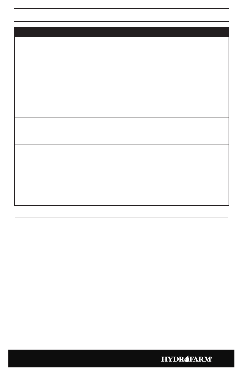
PROBLEM CHECK SOLUTIONS
Screen does not work aer
connecng power supply
Check if the power supply/
adapter/controller works
normally
Unplug DC connector from the
controller momentarily then
reconnect taking care to ensure
the connector is fully inserted
and ghtened
Controller does not control xtures
Check if the signal cable is
connected well and is fully
inserted/locked; check pin
condion
Reconnect the signal cable and
go xture by xture to idenfy
communicaon loss point
Controller does not show
temperature aer connecng with
temperature probe
Check if the temperature
probe is inserted fully
Disconnect and reconnect the
temperature probe
Fixture status is dierent from the
power set by controller
Check if the xture is under
sunrise and sunset mode or
if the temperature is under
temperature protecon mode
Adjust the me of sunrise and
sunset or reset the temperature
limits
When connecng several xtures,
the rst several xtures work
normally, while the following
xtures funcon abnormally
Check if the signal cable is
connected well, or if the
pins of the connectors are
damaged, or the LED status
on xtures
Reconnect the signal cable, or
replace any damaged xture
Fixtures fail to turn o
Check xture quanty per
zone. Too many xtures will
cause residual voltage in the
cable system.
Reduce number of xtures per
zone
TROUBLESHOOTING
See pages 8–23 for data link cable guides that show you how to customize your lighng setup
with the same or mulple lighng technologies within the same environment.
LED Fixtures ............................................................8
HID Fixtures
Phantom with USB .................................................10
Core 2.0 ..........................................................12
Mulple Lighng Technologies
LED + Dual CMH ...................................................14
LED + DE HPS ......................................................15
Dual Zone DE HPS ..................................................16
DE HPS + Dual CMH ................................................20
DE HPS + DE MH ...................................................22

Hydrofarm.com
8
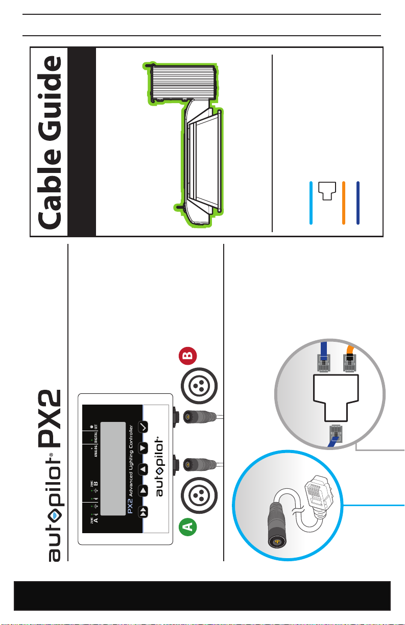
CABLE GUIDE

9
CABLE GUIDE
Hydrofarm.com
10
CABLE GUIDE
Advanced Digital & Analog
Lighting Controller (APDPX2)
Fixtures are not shown to scale.
IMPORTANT: Do not attach data link cables to AC power cable. Always keep low voltage data cables and high voltage AC
power harness as far as possible from each other for stable signal transmission. Avoid coiling data cables as well as AC
harnesses in tight coils. Excess cable should be managed by creating long loops as opposed to tight coils.
RJ Data
Link Cable
RJ12
T-Connector
RJ12 to USB
RJ Data Link Cable
RJ12 T-Connector
RJ12 to RJ12
RJ12 to USB
LEGEND: HPS, MH & CMH
ZONE A
Controls up to
256 HID fixtures.
ZONE B
Controls up to
256 HID fixtures.
PHANTOM with USB
HID Fixtures
Note: Zone A and Zone B
can be set up in one room,
or in two separate rooms.
Altri manuali per Autopilot PX2
2
Questo manuale è adatto per i seguenti modelli
1
Indice
Altri manuali Hydrofarm Controllori

Hydrofarm
Hydrofarm Deluxe CLIMATE Manuale utente

Hydrofarm
Hydrofarm Active Aqua Grow Flow Manuale utente

Hydrofarm
Hydrofarm Autopilot APC8200 Manuale utente

Hydrofarm
Hydrofarm autopilot APCETHA Manuale utente

Hydrofarm
Hydrofarm Autopilot PX2 Manuale utente

Hydrofarm
Hydrofarm APCETHD Manuale utente

Hydrofarm
Hydrofarm Autopilot PX2 Manuale utente

Hydrofarm
Hydrofarm Autopilot APCTART Manuale utente

Hydrofarm
Hydrofarm Autopilot APCL4DX Manuale utente

Hydrofarm
Hydrofarm Autopilot PX1 Manuale utente


