IDTECK Star iCON100 Manuale utente

Quick Installation Guide
Single Door
Access Control Panel

1
Quick Installation Guide
Table of Contents
1. IDENTIFYING SUPPLIED PARTS························································································································ 2
2. RECOMMAND CABLE TYPE AND PERMISSIBLE LENGTH··············································································· 2
3. CHECK POINTS DURING INSTALLATION·········································································································· 3
4. REVERSE DIODE CONNECTION························································································································ 5
5. SYSTEM INITIALIZATION ··································································································································· 5
6. DEVICE SETTING ··············································································································································· 6
7. WIRING ······························································································································································· 9
8. COMMUNICATION ············································································································································ 12
9. PRODUCT MANUAL DOWNLOAD INFORMATION ··························································································· 18

2
Quick Installation Guide
1. IDENTIFYING SUPPLIED PARTS
Unpack and check the contents. If any of these parts are missing, contact your distributor.
Main Unit (1ea) Quick Guide (1copy) Door Lock & ALARM Guide (1Sheet)
Diode (2ea) Resistor2.2k(4ea)
Keypad(Option) LCD Module(Option) TCP/IP Module(Option)
2. RECOMMAND CABLE TYPE AND PERMISSIBLE LENGTH
Reference
Description
Cable Specification
Maximum
Distance
①
iCON100 Power (DC12V)
DC Power -> iCON100
Belden #9409, 18 AWG
2 conductor, unshielded
3m
②*
Reader (Power and Data)
Extra Reader
Belden #9512, 22 AWG
4 conductor, shielded
150m
Belden #9514, 22 AWG
8 conductor, shielded
③
Door Contact
Exit Button
Sensor Input
Input -> iCON100
Belden #9512, 22 AWG
4 conductor, shielded
300m
Belden #9514, 22 AWG
8 conductor, shielded
④
Door Lock,
Alarm Device
Lock (Alarm) -> iCON100
Belden #9409, 18AWG
2 conductor, unshielded
300m
⑤
RS232 Cable
Converter -> Host P.C.
Belden #9829, 24 AWG
2-twisted pair, shielded
15m
⑥
RS422 Cable
iCON100 -> iCON100
iCON100 -> Converter
Belden #9830, 24 AWG
3-twisted pair, shielded
1,200m
* Requires thicker wire if you connect the reader with high current consumption.

3
Quick Installation Guide
3. CHECK POINTS DURING INSTALLATION
3.1 Termination Resistor
Termination resistors are used to match impedance of the network to the impedance of the transmission line being
used. When impedance is mismatched, the transmitted signal is not completely absorbed by the receiver and a portion
of signal is reflected back into the transmission line.
The decision whether or not to use termination resistors should be based on the cable length and data rate used by
the communication system.
For example, if you use 9,600 baud rate and 1,200m length of cable, the propagation velocity of cable is 0.66 x speed
of light (This value is specified by the cable manufacturer), if we assume the reflections will damp out in three round
trip up and down the cable length, the transmitted signal will stabilize 18.6us after the leading edge of a bit. Since the
data bit is captured in the middle of the bit which is approximately 52us after the leading edge of a bit. The reflection
stabilizing time 18.6us is much before the center of the bit therefore the termination resistors are not required.
However, if you install the cable to maximum length, the impedance of cable and network is mismatched and the
transmitted signal is overlapped by the reflected signal. In this case, it is recommended to add termination resistors to
the end of the receiver lines. A 120Ω resistor can be used for termination resistor in parallel between the receiver lines
“A” and “B” for 4 wires RS422 system. A termination resistor of less than 90Ω should not be used and no more than 2
terminations should be used in one networking system.
3.2 How to Connect Termination Resistors
Figure: Termination Resistors for 4 Wire RS422 Communication System

4
Quick Installation Guide
3.3 Grounding System for Communication Cable
We recommend to using proper grounding system on the communication cable. The best method for grounding
system is to put the shield wire of the communication cable to the 1st class earth grounding; however it is not so easy
to bring the earth ground to the communication cable and also the installation cost is raised.
There will be three grounding point where you can find during installation;
1) Earth Ground
2) Chassis Ground
3) Power Ground
The most important point for grounding system is not to connect both ends of shield wires to the grounding system; in
this case there will be a current flow through the shield wire when the voltage level of both ends of shield wire is not
equal and this current flow will create noise and interfere to communications.
For the good grounding, we recommend to connecting Only one end of shield wire of communication cable to
grounding system; If you find earth ground nearby, then connect one end of shield wire to earth ground; If you do not
have earth ground nearby, then find chassis ground and connect one end of shield wire to chassis ground; If you do
not find both earth ground and chassis ground, then connect one end of shield wire to power ground. (GND of
iCON100)
Note that if the chassis ground is not properly connected to the earth and floated from the ground level, then grounding
to the chassis ground will give the worst communication; in this case we recommend to using power ground instead of
chassis ground.
Figure: Grounding System

5
Quick Installation Guide
4. REVERSE DIODE CONNECTION
If you connect an inductor (Door Locks or Alarm device) to the output relays, there will be a high surge voltage created
while the inductor is turning on and off. To protect this problem, connect the reverse diode as the figure below.
Caution
It is strongly recommended to add a reverse diode between the inductor coils to absorb this surge voltage.
If you do not connect a reverse diode, the surge voltage will transfer and damage
the electronic circuit of the controller. 1N4004 –1N4007 or equality efficiency diode is included in gift box.
Figure: Reverse Diode Connection
5. SYSTEM INITIALIZATION
Initialization must be performed before first installation of iCON100. Press down the two initialization switches
simultaneously then keep pressing more than 2 seconds. Once buzzer sound is generated, release the switches then
initialization is done and system restarts automatically.
Figure: Switches Location Figure: Magnification of Switches Figure: LCD Display
Caution
If you initialize the iCON100, all data such as user ID, baud rate, door setting, time schedule and event information
stored in the controller will be cleared and the default values (factory setting values) will be reloaded. Therefore, the
Initialization should be performed by authorized person only. It is recommended to upload all events data before
initialization in case you use events data for time and attendance purpose.
PRESS
SYSTEM INIT.
WAITING !!!

6
Quick Installation Guide
6. DEVICE SETTING
6.1 26Bit / 34Bit Wiegand Setting
Select the data format (26bit/34bit) input to reader port. There is a switch for bit setting on the upper left side of
iCON100 board. The switch is set to ‘OFF’ position as the default (26Bit Wiegand setting). If the switch is set to ‘ON’
position as shown below table, the system is set to 34Bit Wiegand.
26bit Wiegand type format: Using 26bit Wiegand format reader
34bit Wiegand type format: Using 34bit Wiegand format reader
If DIP switch turns from ‘ON’ to ‘OFF’ or ‘OFF’ to ‘ON’, buzzer is generated. If the buzzer doesn’t stop after the DIP
switch is changed, it means ID information or event is stored in the memory. In this case, delete existing ID and event
by initialization then you can change data type of reader port.
Figure: Position of 26/34Bit Wiegand Setting Switch
26Bit Wiegand (Default)
iCON100
34Bit Wiegand
iCON100SR
Figure: 26Bit/34Bit Wiegand Setting Example
Switch for 26/34Bit Wiegand Setting

7
Quick Installation Guide
6.2 Board ID(Communication ID) Setting
Board ID is the unique address to communicate with PC. There is 5 channel DIP switch on the upper left side of the
iCON100 board for board ID setting. Each DIP switch has assigned address value and the board ID is calculated by
the sum value of each switch set to “ON” position. Board ID can be set from ‘0’to ‘31’. The default value of board ID
is’0’(5 channel DIP switch is set to ‘OFF’position). Refer to the example below.
Caution
Each Board ID on the same communication loop must be not duplicated. If the same Board IDs are
on the same loop, the communication error will occur.
Figure: Position of Board ID Setting Switch
Communication ID= 0
(Default)
Communication ID=14
(2+4+8 = 14)
Communication= ID
(1+16 = 17)
Figure: Board ID Setting Example
Board ID Setting Switches

8
Quick Installation Guide
6.3 Baud Rate Setting
Baud rate is the speed rate during communication with host PC. The 3 DIP switches are assigned for baud rate setting
on the upper left side of the iCON100 board. You can select one of 4800bps, 9600bps, 19200bps, 38400bps,
57600bps and 115200bps.You have to set applicable baud rate according to communication environment, and the
connected devices on one loop must have the same baud rate. If DIP switch turns from ‘ON’ to ‘OFF’ or ‘OFF’ to ‘ON’,
buzzer is generated. Also under TCP/IP communication, the baud rate has to be matched with TCP/IP module.
Caution
Baud rate must be the same as the values set by application software and the baud rate of all products on the
same loop must be same.
If you use ver. 6.0 and lower with ver. A1.0 and higher together, set the baud rate to 9600bps only. When you
only use ver. A.1.0 and higher, you can set other baud rate including 9600bps.
If you set high baud rate in bad environment for communication, communication may not properly operate. In
this case, let baud rate lower.
Figure: Position of Baud Rate Setting Switches
(Default)
Figure: Baud Rate Setting Example
Switches for Baud Rate

9
Quick Installation Guide
7. Wiring
7.1 Power
Connect (+) wire of DC 12V power to +12V terminal
Connect GND (-) wire of DC 12V power to GND terminal
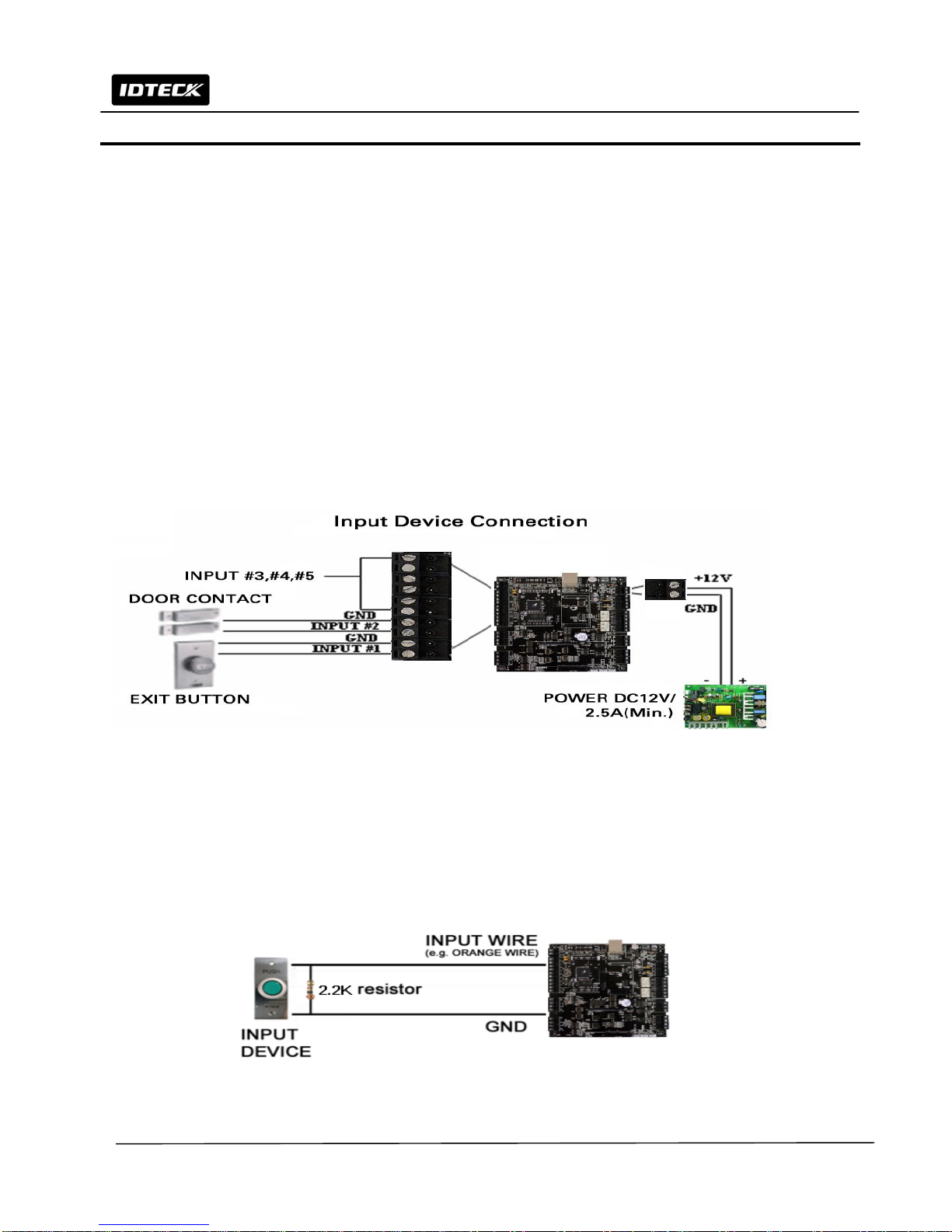
7.2 Input Connections
Exit Button Connection (Input #1)
- Connect one wire from an Exit Button to Input #1
- Connect the other wire from the Exit Button to the GND
Door Contact Sensor Connection (Input #2)
- Connect one wire from a Door Contact Sensor to Input #2
- Connect the other wire from the Door Contact Sensor to GND
Auxiliary Input Connection (Applied to Input #3, Input #4 and Input #5)
- Connect one wire from an Auxiliary Input Device to one of the Input #3, #4 and #5.
- Connect the other wire from the Auxiliary Input Device to GND
Figure: Input Devices Connection
2.2K Resistance Connection for ‘Cut Off Check’
To use the ‘Cut Off Check’ function, you have to connect 2.2K resistance between Input wire (ex. Orange) and GND.
Firstly you choose to use ‘Cut Off Check’. Follow the process as [F2 SETUP MENU] ->”5. IN/OUT DEFINE”
“21.CUT OFF CHECK”. For setting of output, follow the process as [F2 SETUP MENU]->”5. IN/OUT DEFINE” “18.
CUT OFF ALARM”.
Figure: 2.2K Resistance Connection for ‘Cut Off Check’
Altri manuali per Star iCON100
3
Questo manuale è adatto per i seguenti modelli
1
Indice
Altri manuali IDTECK Pannello di controllo