Ijinus LNU06V4 Manuale utente

Installation Guide
Battery powered ultrasonic level sensors
Measurement of water heights

LNU sensor : Installation & programming
Installation Guide
K0J00016
-
EN
-
A0
2
IJINUS – 25 ZA de Kervidanou 3 – 29300 MELLAC – FRANCE - www.ijinus.com - [email protected]m 2
Table of contents
Table of contents ............................................................................................................................................................... 2
1. Introduction .................................................................................................................................................................... 3
2. Three main ranges of measurements (depending on max distance to measure) ....................................................... 3
3. Equipment (4 configuration examples) ......................................................................................................................... 4
a. Temporary Installation................................................................................................................................................ 4
b. Permanent installation of a unique level sensor (continuous monitoring or self-monitoring of water networks) ... 5
c. Permanent installation of several level sensors and a logger (continuous monitoring or self-monitoring of water
networks): ........................................................................................................................................................................... 5
d. Other configurations. .................................................................................................................................................. 5
4. Quick configuration with the software Avelour ........................................................................................................... 6
a. Necessary equipment ................................................................................................................................................. 6
a. Prerequisite ................................................................................................................................................................. 6
b. First step: Run Avelour and connect to the sensor to configure ................................................................................ 7
c. Second step: Selection of the sensor to configure, a firmware update could potentially be suggested ................... 7
d. Third step: Level Measurement Configuration ........................................................................................................... 8
Calibration of the sensor Case N°1 (Ideal) ........................................................................................................................ 11
Calibration of the sensor Case N°2 (Classic example of a manhole with an invert channel) ........................................... 12
Calibration of the sensor Case N°3 (complex) – Expert mode .......................................................................................... 14
e. Fourth step: Data reading in real time...................................................................................................................... 19
f. Fifth Step: Retrieve and see locally your data by radio ............................................................................................ 19
g. Sixth step: Data export ............................................................................................................................................. 20
h. Seventh step: Pair devices ........................................................................................................................................ 20
i. Eighth step: Data sending ......................................................................................................................................... 21
5. Elements for good practice and installation examples ............................................................................................... 24
6. Procedure for inserting the SIM card .......................................................................................................................... 26
7. Procedure for changing the internal battery .............................................................................................................. 27
8. Document History ........................................................................................................................................................ 28

LNU sensor : Installation & programming
Installation Guide
K0J00016
-
EN
-
A0
2
IJINUS – 25 ZA de Kervidanou 3 – 29300 MELLAC – FRANCE - www.ijinus.com - [email protected]m 3
1. Introduction
This Ijinus product unites ultrasonic water height measurement, with automatic measurement cycle changes
depending on threshold values and flow rate transformation through conversion tables. Some sensors are
equipped with connectors for coupling with an overflow detector or to control water sampler.
In addition to measuring, these sensors can also be paired with others or serve as data concentrators by 2G/3G or
2G/4G (LTE-M/NB-IoT).
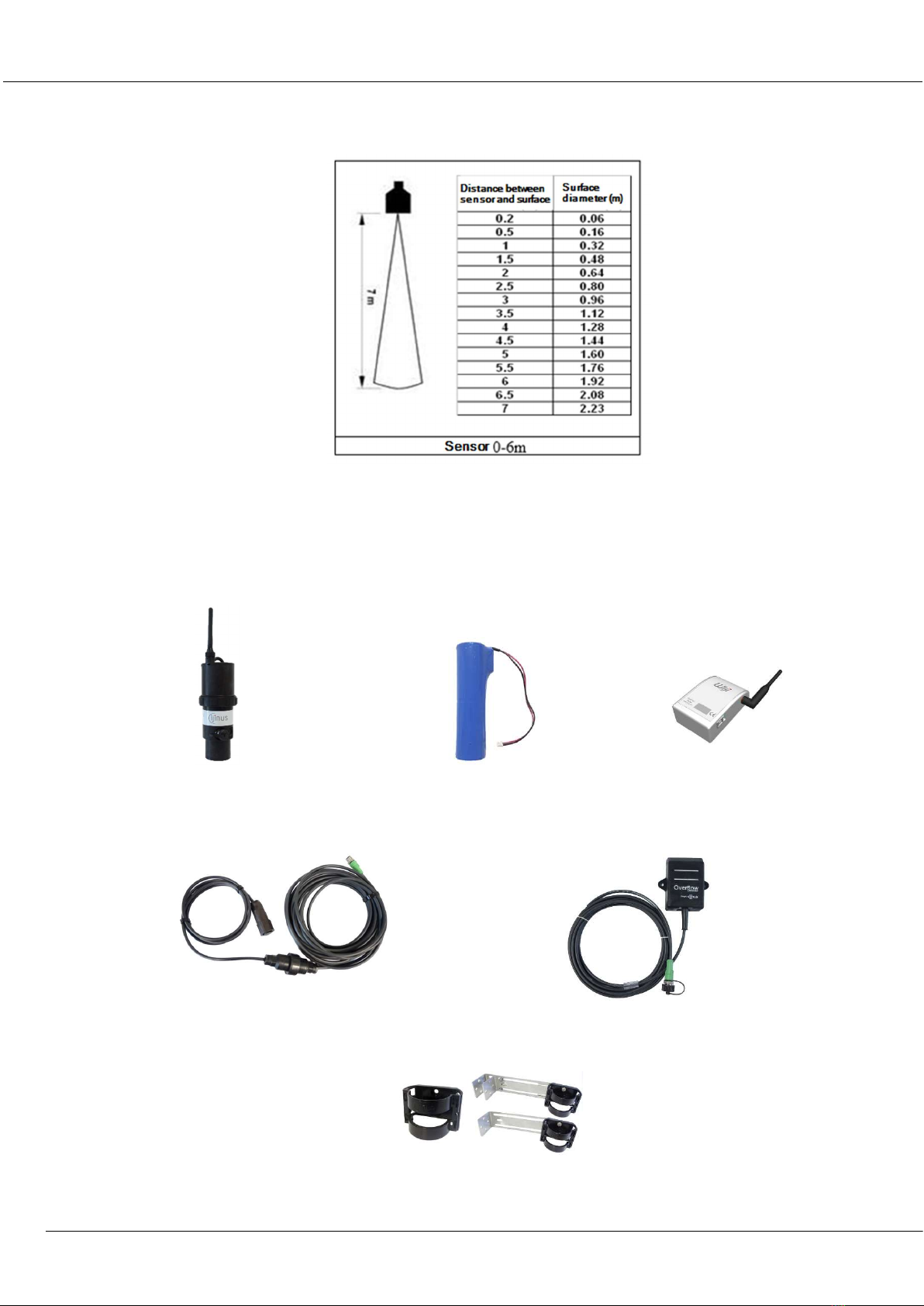
2. Three main ranges of measurements (depending on max distance to measure)
LNU06V4
Measure up to 6m
LOG10V4
Measure up to 10m
External ultrasonic
probe
LNU sensor : Installation & programming
Installation Guide
K0J00016
-
EN
-
A0
2
IJINUS – 25 ZA de Kervidanou 3 – 29300 MELLAC – FRANCE - www.ijinus.com - [email protected]m 4
For example, the figure below shows the diameter of the area that will be studied by two probes models (6 and
10m) as a function of the distance:
3. Equipment (4 configuration examples)
a. Temporary Installation
The sensor is autonomous, and battery powered (lithium battery), it measures water level by air ultrasonic
waves. It has internal logger and data can be retrieved on-site (with radio using the programming kit: Wiji).
Fixations: Bracket, fixations either with single
or double metal plate with bracket
Ultrasonic sensor
Lithium
battery
Programming kit
Water sampler cable
Overflow detector

LNU sensor : Installation & programming
Installation Guide
K0J00016
-
EN
-
A0
2
IJINUS – 25 ZA de Kervidanou 3 – 29300 MELLAC – FRANCE - www.ijinus.com - [email protected]m 5
b. Permanent installation of a unique level sensor (continuous monitoring or self-monitoring of
water networks)
For battery powered level measurement (replaceable lithium) and cellular communication (2G, 3G or 4G depending on
the sensor).
Sensor integrating a logger, cellular communication modem and its external antenna
c. Permanent installation of several level sensors and a logger (continuous monitoring or self-
monitoring of water networks):
For battery powered level measurement (replaceable lithium) and short-range radio communication used with a
second logger to retrieve the data and send them out with cellular communication.
Data logger as a radio/3G access point
d. Other configurations.
Currently, the available communication protocols for the Ijinus devices are the following:
- Radio for a HF configuration and data retrieval: Wiji protocol
- Wireless communication for remote data monitoring: 2G, 3G, LTE-M and NB-IoT
- Wired communication with a PLC: Modbus RS 485

LNU sensor : Installation & programming
Installation Guide
K0J00016
-
EN
-
A0
2
IJINUS – 25 ZA de Kervidanou 3 – 29300 MELLAC – FRANCE - www.ijinus.com - [email protected]m 6
4. Quick configuration with the software Avelour
We will show here the most common way to program the system for level measurement and data sending by
cellular communication.
a. Necessary equipment
- The software Avelour in 7.0 version minimum
- Programing Wiji kit or Wiji key
Avelour
Wiji
kit
Wiji
key
a. Prerequisite
- The equipment should be functional, with a working battery.
- All indications contained in this document refers to programming using Avelour 7.0 minimum

LNU sensor : Installation & programming
Installation Guide
K0J00016
-
EN
-
A0
2
IJINUS – 25 ZA de Kervidanou 3 – 29300 MELLAC – FRANCE - www.ijinus.com - [email protected]m 7
b. First step: Run Avelour and connect to the sensor to configure
After connecting the Wiji kit equipped with its antenna (or the Wiji key) on your laptop or PC USB port, run
Avelour software. Click the button “Connect to a wireless device”. The sensor or logger will be directly visible by
its part number (SN) without the need to activate anything else (ex: IJA0101-0000 3559). Locate the sensor's
serial number (SN) on the sensor label and click "OK".
On the first connection with the sensor only the serial number will appear. During the next connections you will
also see the name of the installation site or another name that you have previously defined.
c. Second step: Selection of the sensor to configure, a firmware update could potentially be
suggested
During its connection with the sensor, the following pop up appears:
When connected, and only if the sensor already has measures in its memory, the following options will suggest
you retrieve the data:
After this, if the sensor is not up to date (case of new firmware developed since your last connection or you are
now connected with a new version of the software Avelour). It is strongly recommended to read carefully the
different messages in the options windows.
The firmware update can take 7 to 12 minutes. It is advised to do it while in your office. On-site, prefer the best
radio connection (avoid the closed metal cover of a manhole).

LNU sensor : Installation & programming
Installation Guide
K0J00016
-
EN
-
A0
2
IJINUS – 25 ZA de Kervidanou 3 – 29300 MELLAC – FRANCE - www.ijinus.com - [email protected]m 8
When the sensors are ready, Avelour will look like bellow:
d. Third step: Level Measurement Configuration
This part is divided in several paragraphs. Each step will be detailed.
General information
This part is useful to describe the measurement point. The most important information would be the name that
will help you to find your sensor for future connections.
Measures
Choice of the application to be configured
This part is the most important, it allows you to configure your sensor.
The simplest way is to click on the button “Add”, then choose “Water height”.

LNU sensor : Installation & programming
Installation Guide
K0J00016
-
EN
-
A0
2
IJINUS – 25 ZA de Kervidanou 3 – 29300 MELLAC – FRANCE - www.ijinus.com - [email protected]m 9
Choice of the measure period
In this new menu, select the measure period (in this example every 5min).
To the right of the measure period selector, 2 little icons allowing a deferred programming according to the
period and day of the week you can choose from. The sensor is not yet calibrated.
Calibration of the water height
After clicking on the “Calibrate” button the following window appears

LNU sensor : Installation & programming
Installation Guide
K0J00016
-
EN
-
A0
2
IJINUS – 25 ZA de Kervidanou 3 – 29300 MELLAC – FRANCE - www.ijinus.com - [email protected]m 10
It is difficult to establish rules but globally 3 cases may arise:
CASE 1: Ideal case: unique echo (test in lab or if the sensor faces flat water surface for example)
A simple calibration will be possible.
CASE 2: Case of a classic manhole with an invert channel at the bottom. The figure bellow shows two echoes (the
invert channel and the water). An advanced mode calibration will be possible. First check that the sensor is well
positioned, facing and perpendicular to the water.
Questo manuale è adatto per i seguenti modelli
1
Indice
Altri manuali Ijinus Accessori


