
Innovative NV200 Manuale utente

Copyright Innovative Technology Ltd 2008 GA620-1
INTELLIGENCE IN VALIDA
T
NV200
OPERATIONS
MANUAL

Copyright Innovative Technology Ltd 2008 GA620-1
CONTENTS
1 Introduction 3
2 Environment and power requirements 5
3 General description 6
4 Machine interfaces 8
4.1 Bezel LED’s 8
4.1.1 Operational colour 8
4.1.2 Diagnostic codes 8
4.2 Hardware 9
4.2.1 Ports and buttons 9
4.2.2 Interface connector pin details 9
4.2.3 USB connection 10
4.2.4 Dip switches 10
4.3 Protocols 10
4.3.1 Smiley®Secure Protocol (SSP) 10
4.3.2 ccTalk®11
4.3.3 MDB (Multi Drop Bus) 12
4.3.4 Parallel 13
4.3.5 Pulse 14
4.3.6 Binary 15
4.3.7 Other interfaces 15
5 Using barcodes 15
6 Reprogramming the NV200 16
6.1 Dataflash® memory cards 16
6.2 Bank note validator currency manager software 17
7 Maintenance and re-initialisation 18
7.1 Routine maintenance 18
7.2 Re-initialisation 18
8 Appendix 19
8.1 Appendix A – How to order a NV200 validator 19
8.2 Appendix B – NV200 mechanical installation 22
8.3 Appendix C – Escrow function 26
8.4 Appendix D – Implemented ccTalk® commands 28
8.5 Appendix E – Parts list and exploded drawings 29
9 Index 31
NV200 Operations Manual
2

Copyright Innovative Technology Ltd 2008 GA620-1
1 INTRODUCTION
This manual describes the operation of the NV200 Bank Note Validator, programmed with
Firmware Version 4.04 or greater.
This document is intended for those who will:
• Install the NV200 equipment.
• Maintain the NV200 equipment
Although information is included which will allow a degree of fault diagnosis and repair, it
is recommended that for all but simple mechanical repairs, the unit must be returned to
an approved service centre for repair.
For more concise information, addressed primarily to maintenance, please refer for the
concise manual in our website.
CAUTIONS
• Never exceed the recommended environmental and electrical limits.
• Do not attempt to lubricate the mechanisms as this may affect the note transport.
• Do not polish the lens as this may alter the optical characteristics.
• If the NV200 validator is disassembled the unit must be re-initialised, following
assembly using LB149 initialisation paper from ITL.
WARNING
• Only suitably trained personnel should carry out any work on this equipment in
accordance with all current local, national and international health and safety
regulations.
We recommend that you study this manual as there are many new features permitting new
uses and more secure applications. If you do not understand any part of this manual please
contact your local office for assistance, contact details are available from www.innovative-
technology.co.uk. In this way we may continue to improve our product.
The NV200 Validator has been designed to minimise any performance variation over time.
Much of this is achieved by careful Hardware and Software design. Innovative Technology Ltd
has a policy of continual product improvement. As a result the products supplied may vary
from the specification described here. This manual can be printed in A4 or letter sizes.
MAIN HEADQUARTERS
Innovative Technology Ltd
Derker Street – Oldham – England - OL1 4EQ
Tel: +44 161 626 9999 Fax: +44 161 620 2090
Web site: www.innovative-technology.co.uk
NV200 Operations Manual
3

Copyright Innovative Technology Ltd 2008 GA620-1
GROUP
EMAIL CONTACT
BRAZIL
CHINA
COLUMBIA
GERMANY
ENGLAND
SPAIN
UNITED STATES OF AMERICA
REST OF THE WORLD
NV200 Operations Manual 4

Copyright Innovative Technology Ltd 2008 GA620-1
2 ENVIRONMENT AND POWER REQUIREMENTS
ENVIRONMENT
POWER REQUIREMENTS
Table 2 – Power Requirements
Table 3 – Interface Logic Levels
It is recommended that a ferrite cable clamp be used on the cable to the NV200, with the cable
having a single turn around the ferrite.
The suggested ferrite is as follows
Manufacturer: Fair-Rite
Manufacturer P/N: 0443166651
Impedance at 100MHz @ 1 turn: 225 Ohms
Environment Minimum
Maximum
Temperature +3ºC +50ºC
Humidity 5% 95% Non condensing
Table 1 – Environmental Requirements
Electrical Supply Minimum
Maximum
Supply Voltage (V DC)
Absolute Limits +11 V +13.5 V
Supply Ripple Voltage 0 V 0.25 V @ 100 Hz
Supply Currents:
Standby 0.4 A
Validating 1.5 A
Peak (Motor Stall) 3.0 A
Interface Logic Levels Logic Low
Logic High
Inputs 0 V to + 0.5 V +3.7 V + 12 V
Outputs with 2K2Ωpull up 0.6 V Pull up voltage of host interface
Maximum Current Sink 50mA per output
NV200 Operations Manual 5

Copyright Innovative Technology Ltd 2008 GA620-1
3 GENERAL DESCRIPTION
The NV200 is the next generation of note reader from
Innovative Technology Ltd.
· Simple, quick re-programming (approximately 30
seconds) with 128 bit encrypted memory card, PIN
number protected
· Up to 16 channels (Depending on mode of operation)
· Secure dual lock cash box with 500 used note capacity
· Seamless note path
· Can accept notes up to 85mm wide and 167mm long
· Seconds note to note
· Reads industry standard barcodes in any direction
· Note centring and straightening mechanism
· Single note escrow function
· User definable colour for bezel illumination
Figure 1 - The NV200 validator
Table 4 – General Specification
ACCESSING
In the Appendix B – NV200 Mechanical Installation you can find a detailed explanation for
cash box removal, note path access, bezel installation and validator head unit removal.
Note sizes accepted Width: 60 – 85mm, Length: 115 – 170mm
Weight 2.8kg
Note to note time 3 seconds
Escrow Single note
Cash box capacity 500 street grade notes
Interface SSP, Parallel, Pulse, Binary, ccTalk, MDB.
(Contact ITL for other interface availability)
Cash box
Note path access
Head unit removal
Bezel installation
NV200 Operations Manual 6

Copyright Innovative Technology Ltd 2008 GA620-1
MOUNTING
The NV200 can be mounted via the mounting holes on either side of the chassis using 4 x M4
fixing screws and a suitable mounting bracket. See drawing number GA604 in Appendix B –
NV200 Mechanical Installation for the location of the mounting holes.
NOTE:
• The length of the screw must be no more than 6mm plus the thickness of the
mounting bracket.
It is also possible to mount the NV200 via fixing holes in the rear of the chassis. Care must be
taken not to obstruct the cash box when using the rear fixing holes. We do not recommend
mounting from the base unless the NV200 is also supported from the back.
LOCK INSTALLATION
The NV200 has the provision of fitting three locks for extra security. One lock can be added to
the front of the NV200 that locks the validator head and cash box into position without the
need of external brackets. Another two locks can be added to the cash box itself.
The cams required for the lock are supplied with the NV200 attached to the back of the lock
blanking plugs. For lock fitting instructions, see drawings numbers GA605 and GA606 in
Appendix B – NV200 Mechanical Installation for the location of the mounting holes.
Suggested lock: - ITL part number PA650; Camlock part number 28D181CPA
ORDERING INFORMATION
When ordering NV200 the following information must be specified:
NV200 EUR01 404 CCT 255 255 255 N 12345 0 123456
Product
Dataset
Firmware
Version
Firmware
Interface
Red LED
brightness
Green LED
brightness
Blue LED
brightness
Bezelflash
Memory
Card PIN
Number of
re-tries
CcTalkkey
Figure2 - Order Code Example
For detailed information on how to order a NV200 validator and use of the ordering template,
refer to Appendix A - How to order an NV200 validator.
NV200 Operations Manual 7

Copyright Innovative Technology Ltd 2008 GA620-1
4 MACHINE INTERFACES
Machine Interfaces
4.1 BEZEL LED’S
4.1.1 OPERATIONAL COLOUR
The operational colour of the bezel illumination can be set to a user definable colour by using
the BNV Currency Manager Software. Each of the three colours of LED in the bezel can be set
to a different brightness level (0-255) to achieve the desired colour. The colour is selected
using the sliders in the Tools menu of the Bank Note Validator Currency Manager Software.
The default colour for the bezel is Magenta
Examples:
Red – 200, Green – 125, Blue – 255
Red – 255, Green – 255, Blue – 0
The Bezel LED’s can also be set to either permanently on or flashing at a rate of once per
second when the note validator is enabled.
Re-programming the NV200 with a memory card that has been programmed using the NV
Card Utilities software will also set the colour and operation of the LED’s.
4.1.2 DIAGNOSTIC CODES
If the NV200 detects an error that is preventing normal operation, the Bezel LED’s will indicate
the cause of the problem by flashing in a certain sequence as shown in Table 5 - Bezel LED
Diagnostic Codes. The LED’s will first flash red a number of times (at 300ms intervals) to
indicate the general area of the problem, then flash blue a number of times (at 120ms
intervals) to give a more exact cause. The full sequence repeats after a pause of 700ms.
Table 5 - Bezel LED Diagnostic Codes
Number of RED
flashes
Number of BLUE flashes
1 2 3 4
1 Note Path Open Note Path Jam Unit Not
Initialised
2 Cash Box
removed
Cash Box Jam
3 Firmware
Checksum
Interface
checksum
EEPROM
Checksum
Dataset
Checksum
4 PSU too Low PSU too High Card Not
Formatted
NV200 Operations Manual 8

Copyright Innovative Technology Ltd 2008 GA620-1
16
15
1
2
4.2 HARDWARE
4.2.1 PORTS AND BUTTONS
Figure 3 - Connector And Switch Location
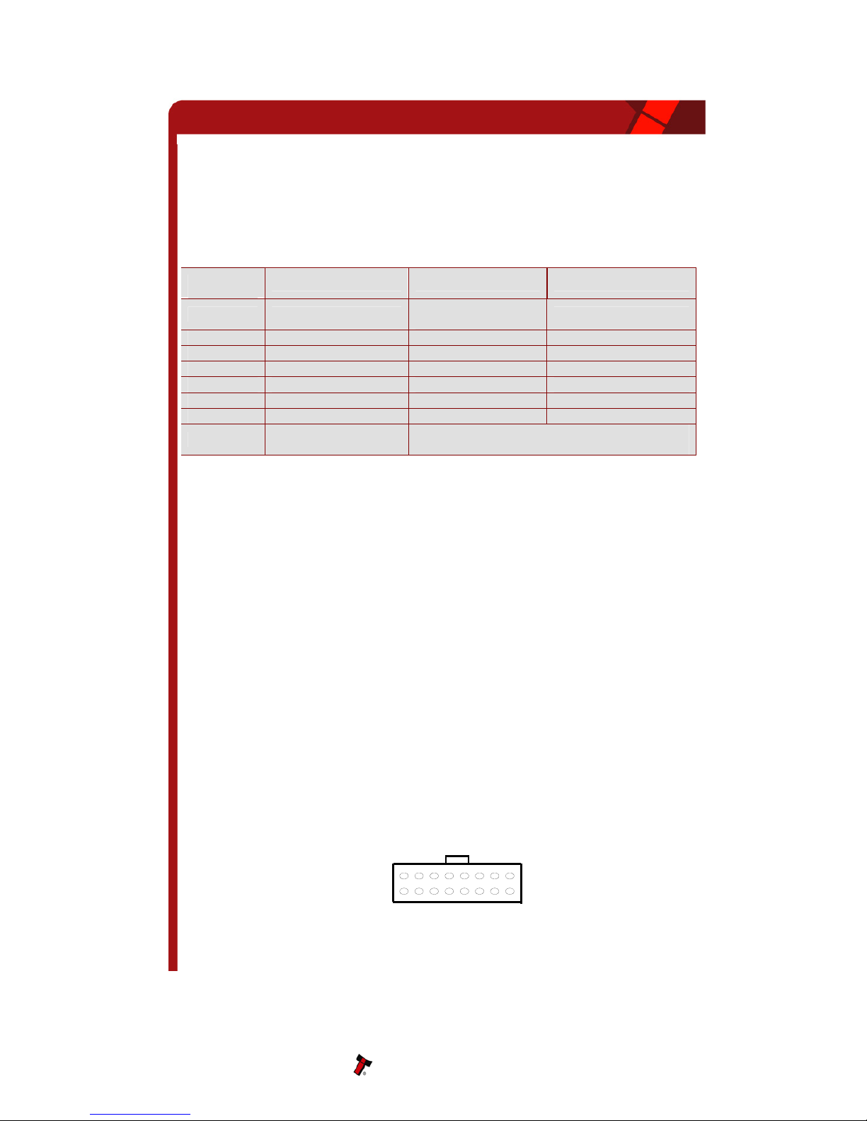
4.2.2 INTERFACE CONNECTOR PIN DETAILS
The function of pins 1-8 changes according to which
machine interface is being used. See the individual
interface descriptions for details. Figure 4 – Pin detail
Pin Name Type Description
1 Vend 1 Output
2 Vend 2 Output
3 Vend 3 Output
4 Vend 4 Output
Open collector outputs. Function changes
depending on machine interface protocol (see
individual interface descriptions for details)
5 Inhibit 1 Input
6 Inhibit 2 Input
7 Inhibit 3 Input
8 Inhibit 4 Input
Inputs are held high to internal +5V via 10KΩ.
Function changes depending on machine interface
protocol (see individual interface descriptions for
details)
9 Busy Output Active LOW when the NV200 is transporting,
reading or stacking a note
10 Escrow Input Enable the escrow function by holding LOW in
Parallel, Pulse or Binary modes (See 8.3 APPENDIX
C – ESCROW FUNCTION)
11 - - Do not connect
12 - - Do not connect
13 Factory Use Only Do not connect
14 Factory Use Only Do not connect
15 +Vin Power Nominal 12V DC supply
16 0V Ground 0V supply
Table 6 – 16 way External Connector Pin Out
It is recommended that a ferrite cable clamp be used on the cable to the NV200, with the
cable having a single turn around the ferrite. See chapter 2 Environment and Power
Requirements for more details on the suggested ferrite.
NV200 Operations Manual 9
Copyright Innovative Technology Ltd 2008 GA620-1
4.2.3 USB CONNECTION
The USB port function is currently under development. Details will be added here when
available
4.2.4 DIP SWITCHES
The bank of 8 dip switches have the following function:
Switch
No Function Switch OFF (Ø) Switch ON (×)
1 Disable Barcode Barcode read
enabled Barcode read disabled
2 Channel 1 Inhibit Channel 1 enabled Channel 1 disabled
3 Channel 2 Inhibit Channel 2 enabled Channel 2 disabled
4 Channel 3 Inhibit Channel 3 enabled Channel 3 disabled
5 Channel 4 Inhibit Channel 4 enabled Channel 4 disabled
6 Channel 5 Inhibit Channel 5 enabled Channel 5 disabled
7 Channel 6 Inhibit Channel 6 enabled Channel 6 disabled
8 Programming Mode Switch from OFF to ON and back to OFF to
activate
Table 7 - Dip Switch Functions
4.3 PROTOCOLS
4.3.1 SMILEY®SECURE PROTOCOL (SSP)
SSP is a secure serial interface specifically designed to address the problems experienced
by cash handling systems in gaming machines. Problems such as acceptor swapping,
reprogramming acceptors and line tapping are all addressed. This interface is
recommended for all new designs.
The interface uses a master slave model, the host machine is the master and the
peripherals (note acceptor, coin acceptor or coin hopper) are the slaves.
Data transfer is over a multi-drop bus using clock asynchronous serial transmission with
simple open collector drivers. The integrity of data transfers is ensured through the use of 16
bit CRC checksums on all packets.
SSP mode can be activated temporarily for the purpose of re-programming the NV200. This
is done by switching DIP Switch 8 ON then OFF again.
NOTE: This mode can only be cancelled by re-programming via the Bank Note Validator
Currency Manager software. Please ensure you are aware of all the NV200 programmed
settings before entering this mode. Failure to restore the original setting will stop the NV200
from operating in the host machine
NV200 Operations Manual 10
16
15
1
2
Altri manuali per NV200
2
Indice
Altri manuali Innovative Validatore di banconote

Innovative
Innovative BV20 Manuale utente

Innovative
Innovative NV9 Manuale utente

Innovative
Innovative BV20 Guida utente

Innovative
Innovative BV100 Manuale utente

Innovative
Innovative NV200 Manuale utente

Innovative
Innovative NV200 Guida utente

Innovative
Innovative BV20 Guida rapida

Innovative
Innovative BV50 Guida utente

Innovative
Innovative NV9 Manuale utente

Innovative
Innovative BV50 Manuale utente


