
Insane Audio JL4001 Manuale utente


Safety Precautions
Before you use this product, be sure to carefully read this
Installation Manual and the separate User’s Guide to
ensure product is installed and used properly. Insane
Audio is not responsible for any problems that arise as a
result of failure to follow the instructions provided.!
This manual includes a number of symbols that are
intended to help you use the product safely, to prevent
harm to you, others and protect against any property
damage. These symbols and their meanings are listed
below. Make sure you fully understand these symbols
before you begin the installation.!
Disconnect the negative battery terminal before
beginning installation.!
Explanations of Injury and Damage That May
Result from Incorrect Use
WARNING
Ignoring the content marked by
this indication and using the
product incorrectly is expected to
lead to death or serious injury.
CAUTION
Ignoring the content marked by
this indication and using the
product incorrectly is expected to
lead to death or serious injury.
Warnings
Do not unassemble or modify the product. Doing so
could lead to an accident, fire or electrical shock.!
Store screws and other small objects where children
cannot reach them. If a small object is swallowed,
consult with a doctor immediately.!
When replacing fuses be sure to use the fuses with the
specified current rating. Failing to do so could lead to an
accident or fire. Only connect the product to a 12V DC
negative ground car. Failing to do so could lead to an
accident or fire.!
Since this vehicle has two batteries, disconnecting the
battery is not a good option. Take caution when testing
circuits. Failing to do so could lead to electric shock or
injury.!
Do not cut the insulation on a cord and take power from
another device. Doing so could lead to fire or electric
shock.!
Do not install the product in a location where it will
obstruct the driver?s forward view; interfere with the
operation of the steering wheel, gear shift, or the like; or
pose a threat to passengers. Doing so could lead to an
accident or injury.!
When making a hole in the vehicle body, be careful to
avoid damaging pipes, the fuel tank, electrical wiring,
and the like. This kind of damage could lead to an
accident or fire.!
When installing and grounding the product, do not use
any of the bolts or nuts of the steering wheel, brakes,
fuel tank, or the like. Doing so could make the brakes
stop working or could lead to fire.!

Warnings
Do not install the product near the passenger-side
airbag. Doing so could interfere with the operation of the
airbag and lead to an accident or injury.!
Bundle cords so that they don't interfere with driving.
Wrapping cords around the steering wheel, gearshift,
brake pedal, or the like could lead to an accident or
damage equipment.!
Caution
Connect the product properly according to the
instructions. Failing to do so could lead to fire or an
accident.!
Do not sandwich cords between the seat railing or allow
them to touch protrusions. Resulting breaks or shorts
could lead to electric shock or fire.!
Do not block vents or heat sinks. Doing so could lead to
fire or damage equipment.!
Use the accessories according to the instructions, and
attach them securely. Failing to do so could lead to an
accident or damage equipment.!
Do not install the product where it may be exposed to
water or in a place with high levels of humidity or dust.
Doing so could lead to fire or damage equipment.!
Introduction
Congratulations on purchasing the JL4001. This manual is
intended to give instructions for installation. !
PLEASE USE YOUR NEW JL4001 RESPONSIBLY. Never
attempt to operate the unit or view videos while driving.
While driving, always keep both hands on the wheel and
your eyes on the road! !
Should you run into problems or need any additional
assistance, feel free to drop us an e-mail at
Once you get your JL4001 installed, a helpful document is
our Quick Start Guide which will walk you through the user
interface.!
Enjoy your new JL4001 and we’II see ya’ on the trail! !
SCAN ME
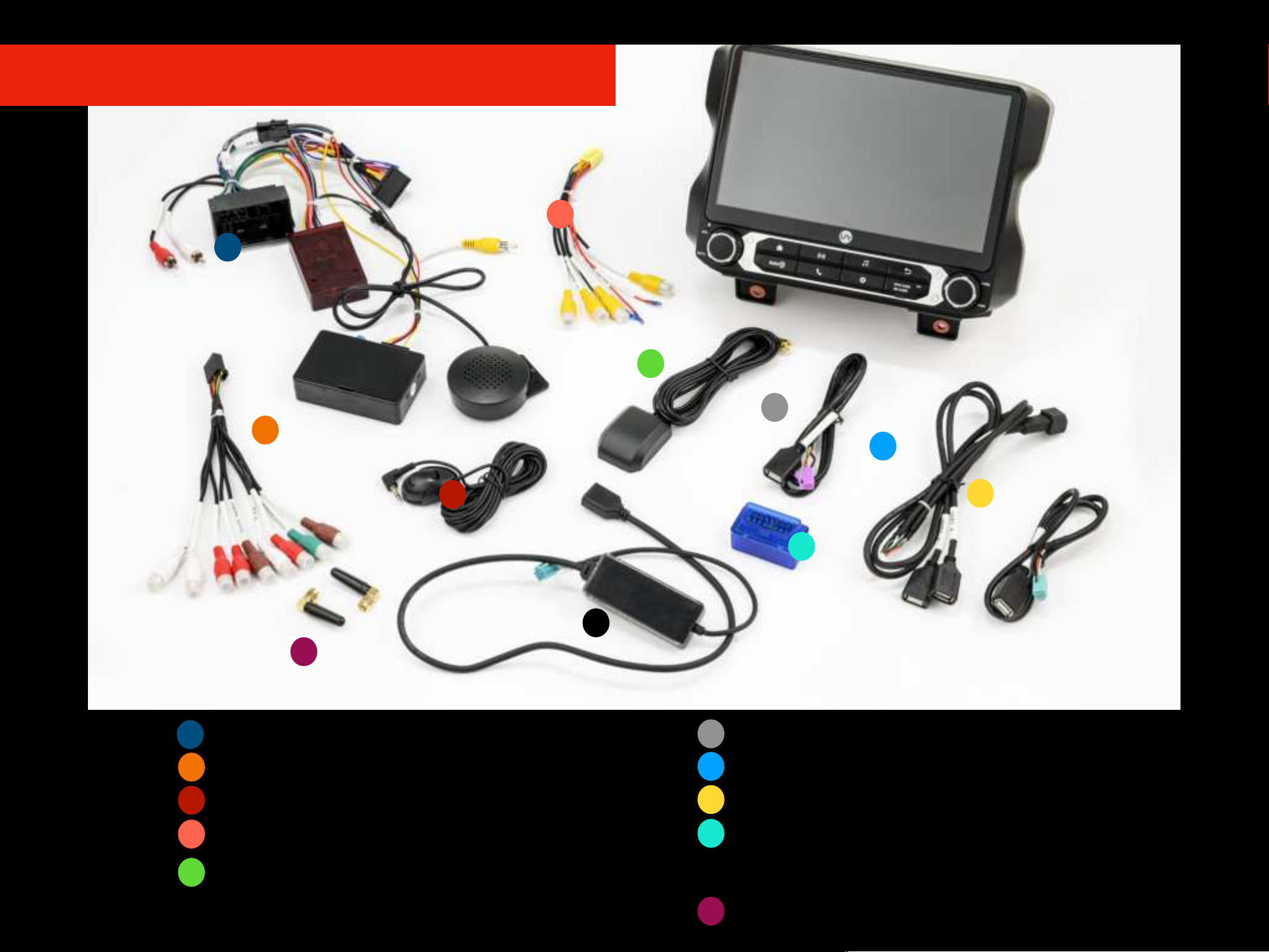
Parts List
A
B
C
D
E
F
G
H
I
J
A
B
C
D
E
F
J
G
I
H
Main Wiring Harness!
Audio RCA Wire Harness!
External Microphone!
RockCam Camera Harness!
GPS Antenna
USB Wire Harness!
USB Wire Harness!
USB Wire Harness!
OBDII Adapter!
IA CarPlay/Android Auto Wire Harness!
One Bluetooth & One WiFi Antenna!
K
K
JL4001

Opening the Dashboard
Unsnap the 6 clips and remove the Knee Panel under
the Steering Wheel using a Panel Removal Tool.
As a precautionary measure it’s a good idea to mask out the
dashboard and panels to prevent scratches.
1
2
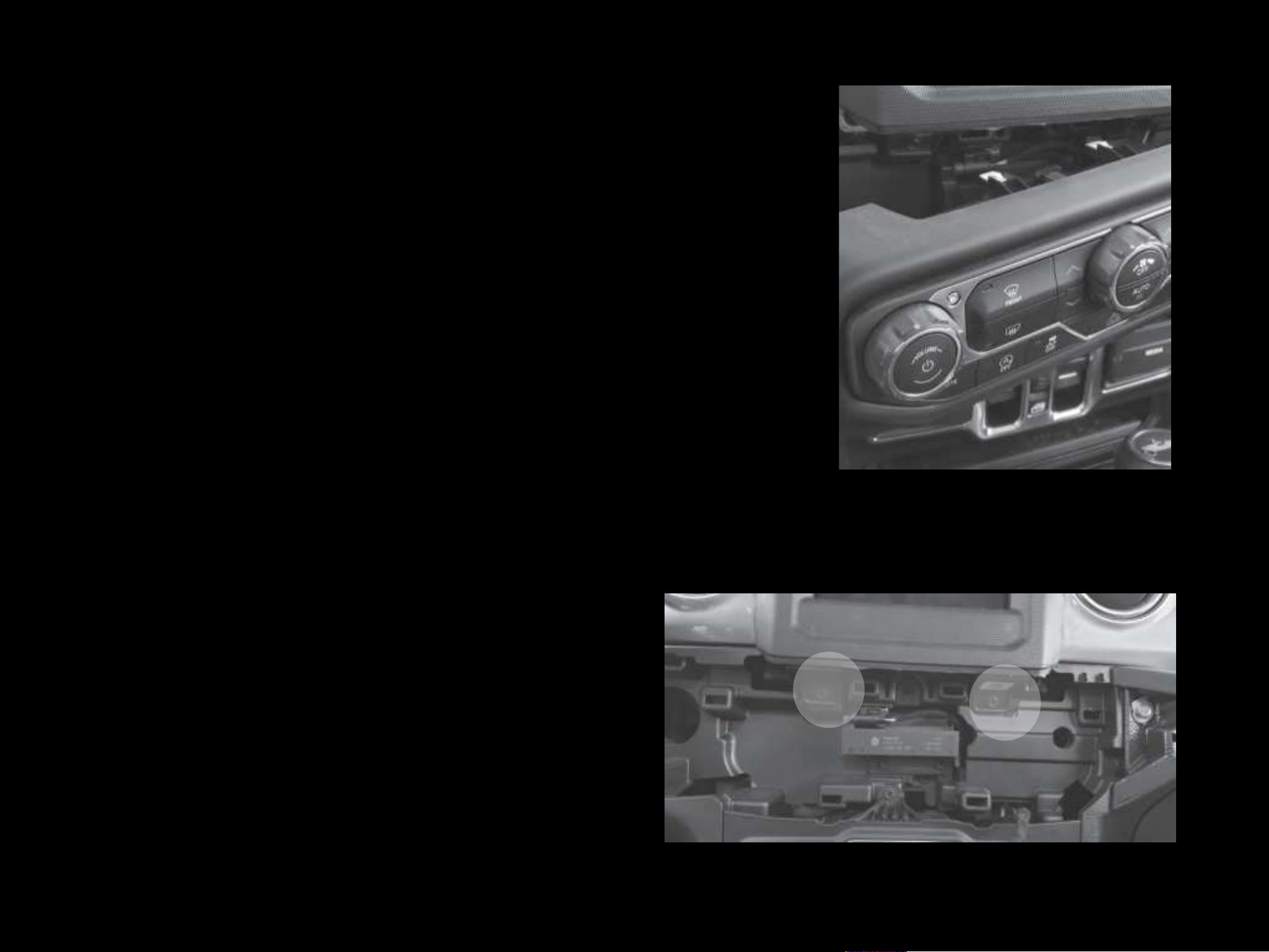
Opening the Dashboard
Use the #2 Phillips Screwdriver to extract the (2)
screws from the bottom of the Radio Bezel.
Unsnap the 10 clips, unplug the 2 harnesses, and remove the
HVAC panel using a Panel Removal Tool.
3
4
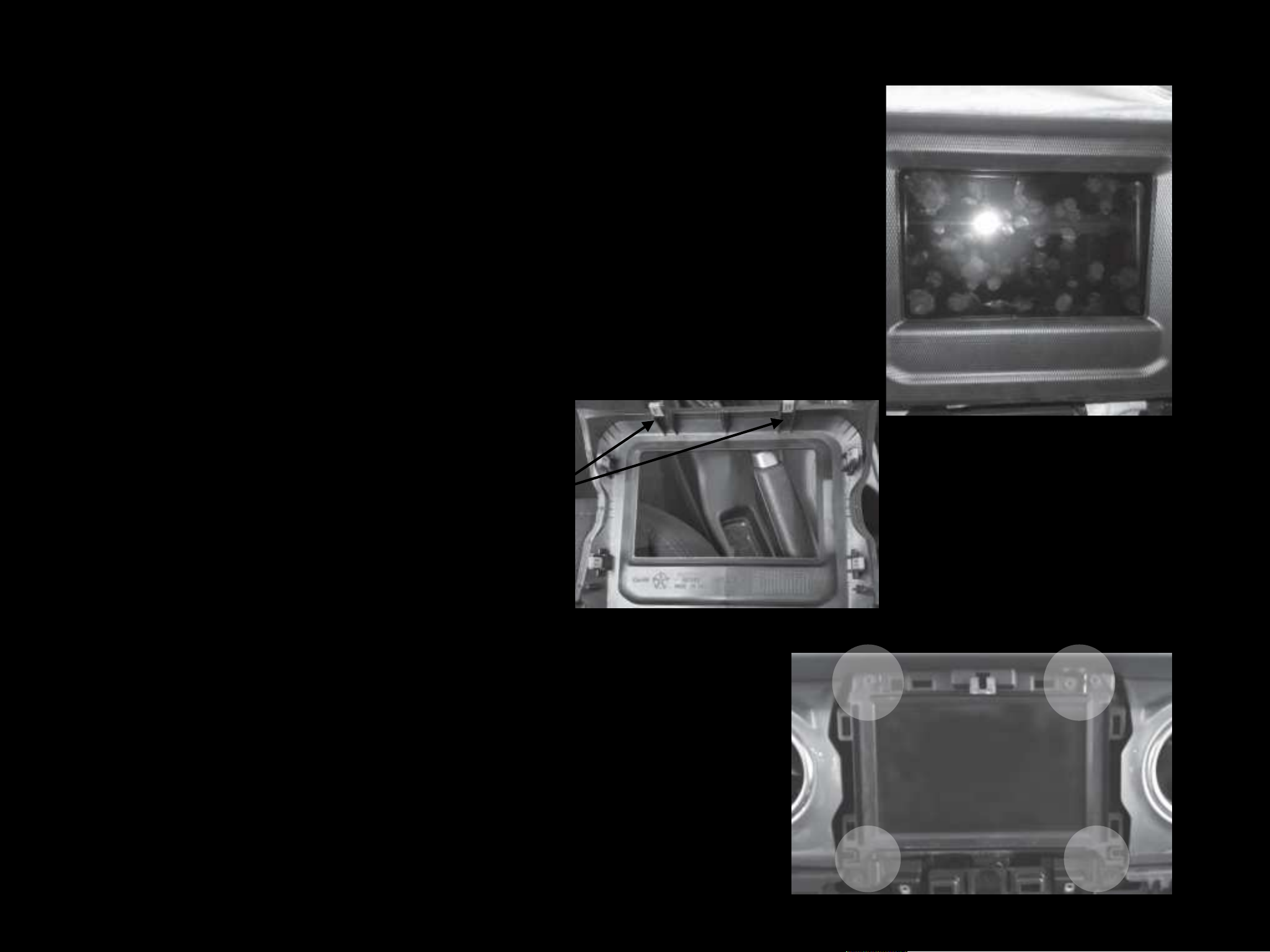
Opening the Dashboard
Use the #2 Phillips Screwdriver to extract the (4) screws from Head
Unit. Disconnect and remove the Radio.
Unsnap the 6 clips and remove the Radio Bezel using a Panel
Removal Tool.
5
6
NOTE: Use the two clips from
OEM Radio Bezel for the JL4001
frame.

Removing OEM Head Unit
The disconnected harness and wires from the previous
step will be used later to connect to the main harness in
the installation. The yellow connector is a SiriusXM
Antenna that is no longer used.
Disconnect the OEM Power Harness, SiriusXM Radio Antenna
connector (yellow), rear OEM Factory Camera Wire Connector
(red), OEM AUX Input Connector (gray) from behind the OEM
Head Unit.
7
8

Installing the JL4001
At the radio cavity, connect the Bluetooth, WiFi and GPS Antennas and
make sure they are secure.!
At the radio cavity, connect the Main Harness, the white OEM AM/FM
Antenna, and any other USB and/or A/V Wire Harnesses and secure them.
Connect the red OEM Rear Camera Wire to the Black Camera Module Box
located on the JL4001 Main Power Wire Harness and make sure it is
secure.
9
10
AM/FM Connector
Camera Module Box
AM/FM Radio Connector
OEM AM/FM Radio Antenna
Bluetooth, WiFi and GPS Terminals

Installing the JL4001
If you DO have the OEM Alpine Premium Sound
System, you will need to swap the speaker quick
connect wires shown in the picture. Connect F2 to
R1 and R2 to F1.
Before proceeding with the installation, vehicles with
the OEM Alpine Premium Sound System will need to
make a minor change on the Main Wiring Harness.
NOTE: FOR VEHICLES THAT HAVE
THE ALPINE PREMIUM SOUND
SYSTEM
Main Power Wire Harness
For OEM Alpine Premium Sound System:
NOTE: If your vehicle is not equipped with the OEM
Alpine Premium Sound System or if you are using your
own aftermarket amps and speakers you do not have to
make any changes. F2 should be connected to F1
and R2 should be connected to R1 as shown in picture.
F2 - F1 Connection (Labeled)
R2 - R1 Connection (Labeled)
CAUTION
Indice
Altri manuali Insane Audio Ricevitore per auto


