INSIGHT IS-DM220/IR/HB Manuale utente

IS-DM220/IR/HB
IS-DM220
Installation
Guide
Indoor/Outdoor
Ver. 1.2
00P6NX223ZXSEA2

2
Table of Contents
1. Indoor Camera
Installation..................................................................................................... 3
1.1 Hard
Ceiling...................................................................................................................
3
1.2 In-Ceiling (T-Bar)
Mounting
.........................................................................................
13
1.3 4S Mount Electrical Box
..............................................................................................
22
1.4 Corner
Mounting..........................................................................................................
25
2. Outdoor Camera
Installation................................................................................................ 29
2.1 Standard/CompactPendant
Mounting........................................................................
29
3. Cable Gland
Installation
....................................................................................................... 34

3
1. Indoor Camera
Installation
1.1 Hard Ceiling
The Fixed Dome IS-DM220 can be installed directly on a wall or ceiling. Please
note that the wall or ceiling must have enough strength to support the IP Dome
Camera.
Items Needed:
z
Vandal Proof/Lightweight Fixed Dome IS-DM220
z
Ethernet Cable
z
DC Jack Cable (supplied; only necessary if not using PoE)
z
Self-tapping Screws (supplied)
z
Rubber Washers (supplied)
z
Plastic Screw Anchors (supplied)
Tools Needed:
z
Tool for drilling
z
(+,–) Screw Drive
4
Follow the steps below to install the IP Dome Camera:
Step 1:
Unpack the IS-DM220/IR/HB IS-DM220 package and take out the IP Dome
Camera.
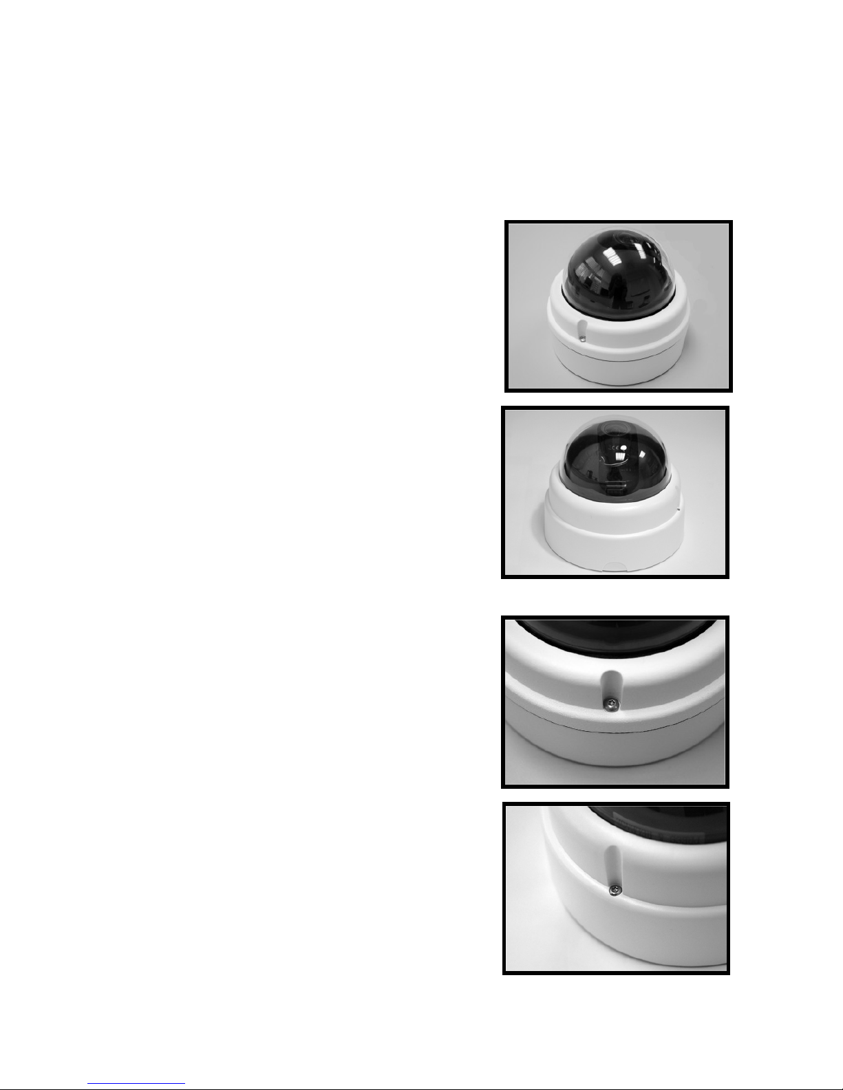
Step 2:
Release the 2 captive Security Screws with
the supplied Security Torx and open the
Dome Cover.
Figure-1:
Captive Security Screw
5
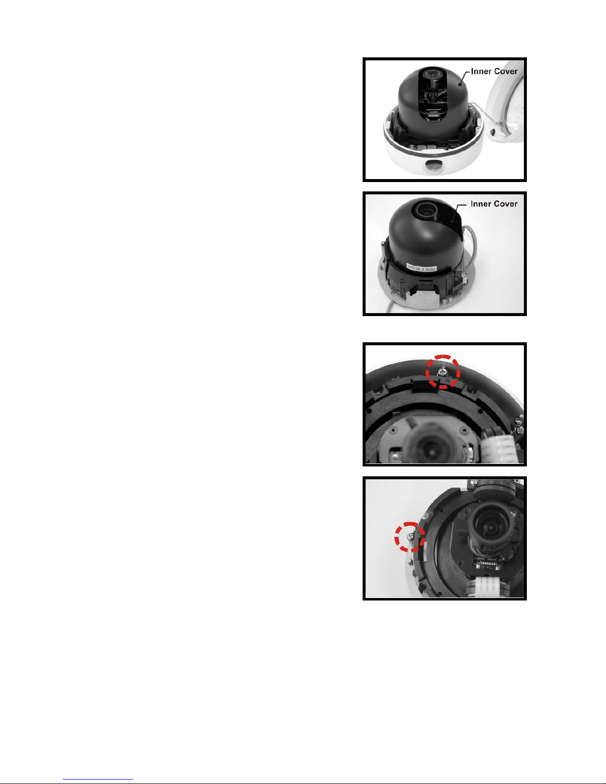
Step 3:
Press both sides of the Inner Cover and
remove it from the Camera Module.
Step 4:
Unscrew the Module-fastened Screw, as
indicated in the figure, with the screw
driver.
6
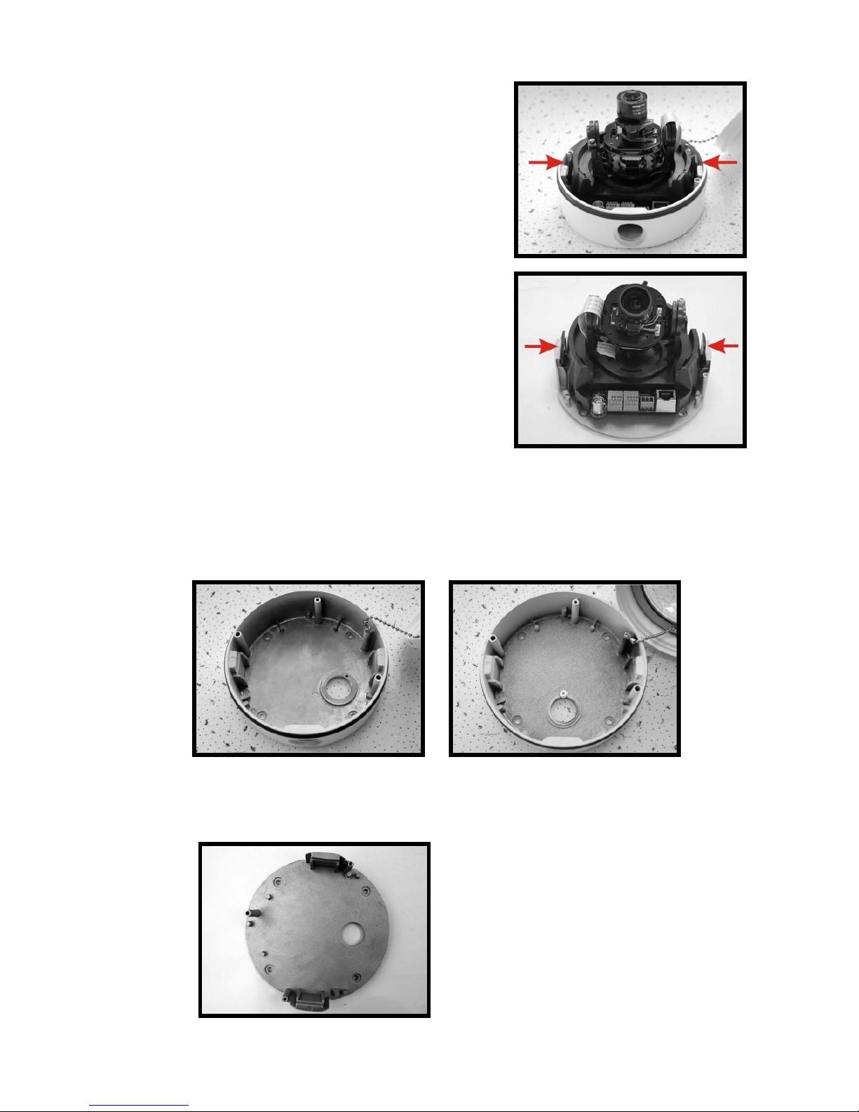
Step 5:
Press the sides of the Snap-on Camera
Module, as indicated in the figure, and
detach it from the Dome Camera’s
Housing/ Plate.
Step 6:
Mark the positions of the four screw holes on the base of the Dome Camera at
the chosen installation location.
Vandal Proof IP Dome Camera
Type 1 Type 2
Lightweight Fixed Dome IS-DM220
7
Step 7:
In the marked locations, drill each hole slightly smaller than the supplied
Screw Anchors.
Step 8:
Put supplied Anchors into these drilled holes.
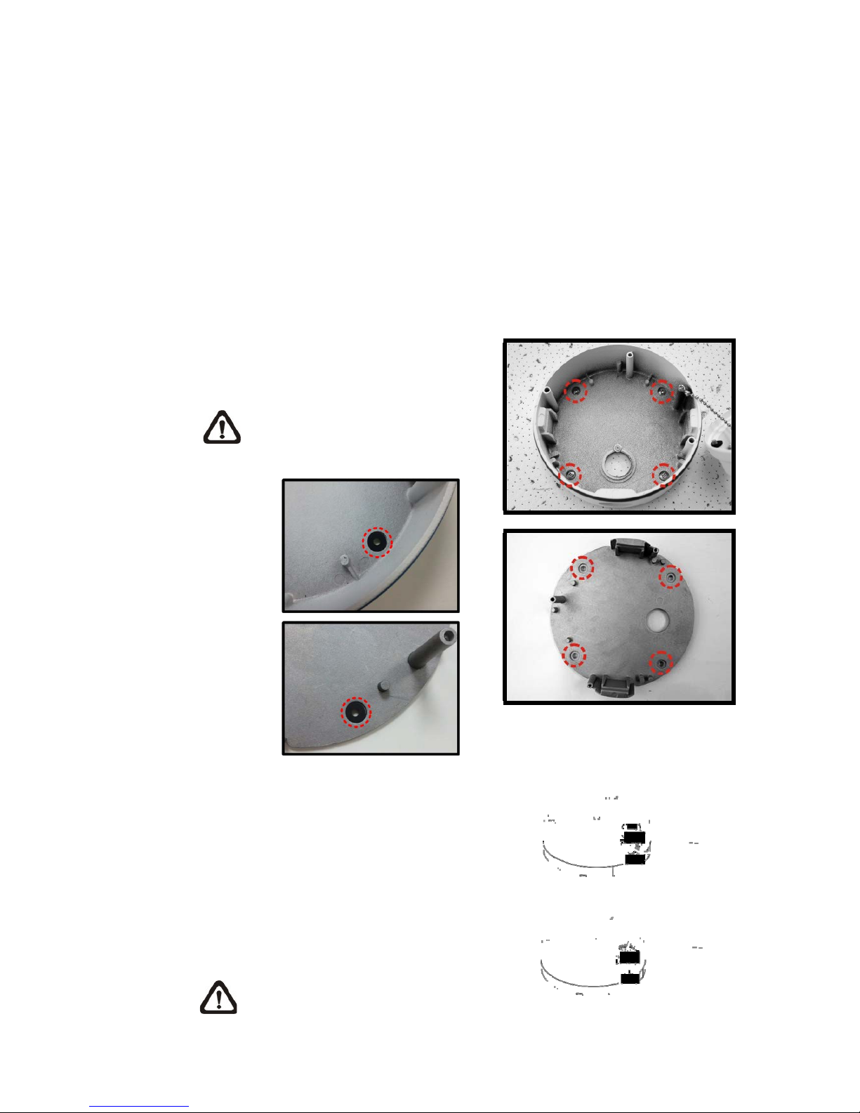
Step 9:
Fasten the Dome Camera’s Housing/
Plate with the four supplied Self-tapping
Screws.
NOTE: Be sure to fix the Self-
tapping Screws with the Rubber
Washers.
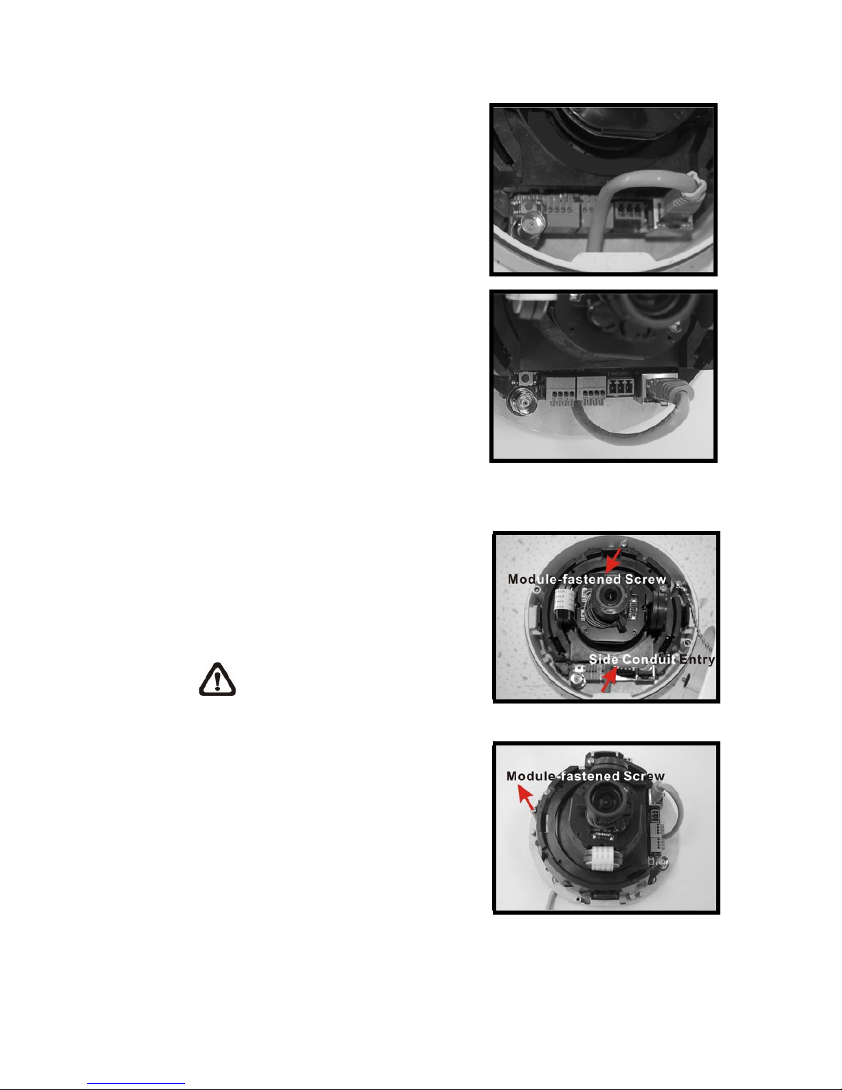
Step 10:
Thread the cables (Power/ Ethernet/
Audio/ Alarm) through either the side
conduit entry or back conduit entry, as
illustrated. Users may use a coin to
screw off the conduit entry block for
Vandal Proof IP Dome Camera.
NOTE: The Power Cable is
omitted if using PoE.
8
Connect the Cable(s) to the Unit
Connect the ports (on the Camera
Module) with their cables/wires
respectively, as shown in the figures.
Step 11:
Attach the Snap-on Camera Module
into/ on the Dome Camera Housing/
Plate, and screw the Module-fastened
Screw tightly with the screw driver to
secure the Camera Module.
NOTE: The terminal blocks
should face the side conduit
entry for Vandal Proof IP Dome
Camera, as shown in the figure.
Vandal Proof
Lightweight
9
Step 12:
Connect the power and network outputs.
NOTE: The Power Cable is omitted if using PoE.
STEP 13:
Access the Camera Browser-viewer for viewing images. Please refer to
User’s Manual for further details. Users can also use the Camera’s BNC
Connector for video output while choosing BNC as one streaming in
advance.
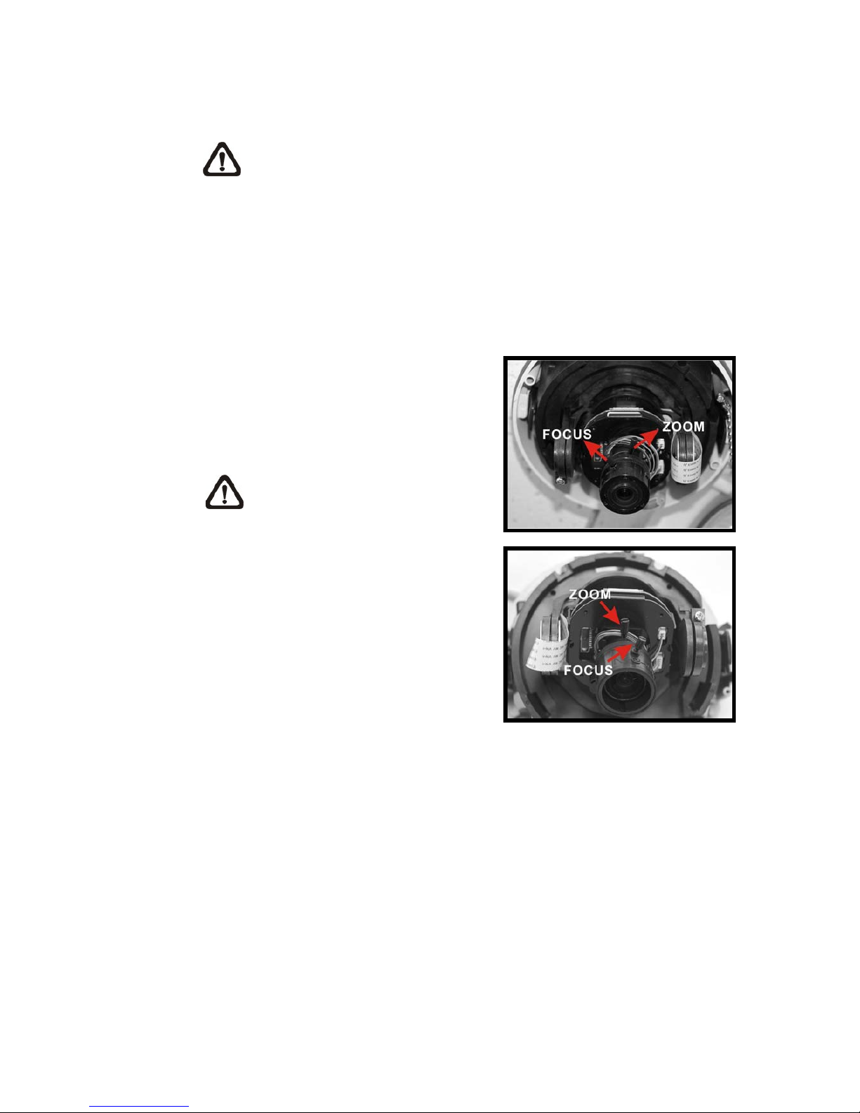
Step 14:
Adjust the Camera's zoom level and
focal length via Zoom and Focus Ring
Screws.
NOTE: The zoom level and focal
length might be different with the
Dome Cover on, in this case,
adjusting zoom level and focal
length through the Dome Cover
is recommended.

10
Adjust the Zoom Ring Screw to set the
desired zoom; subsequently, modifying
the Focus Ring Screw to set the desired
focal length.
Step 15:
Adjust the Camera’s Pan/Tilt holder to a desired angle, as shown below. Pan
adjustment range is nearly 360°; rotation angle range approaches to 270°.
Tilt is adjustable between ﹣10° ~ 90°.
Pan Adjustment Tilt Adjustment
NOTE: Adjust the Lens carefully within the limits mentioned above, or
the cables underneath would be harmed.
Questo manuale è adatto per i seguenti modelli
1
Indice


