Insignia IN-MP101 Manuale utente

User Guide | Guía del Usuario | Guide de l’utilisateur
English Descriptor | French Descriptor| Spanish Descriptor
IN-MP101

Page 2 http://www.insignia-products.com
Model IN-MP101

OWNER’S MANUAL
Mobile Audio System
• PLL Synthesizer Stereo Radio
• Digital Compact Disc Player/MP3 Player/WMA Player
• Automatic Memory Storing
• Fold Down Detachable Panel
• Preset Equalization
• Electronic Shockproof (ESP) Function
• USB Interface
• Auxiliary Input Function
• Remote Control

Installation .....................................3
Take out screw before installation...3
DIN Front-Mount (Method A) ..........3
Installing the unit..........................3
Removing the unit........................4
DIN Rear-Mount (Method B) ...........5
Using the detachable front panel 6
Wiring Connection ........................7
Operation .......................................8
Location of keys..............................8
Switching on/off the unit.................9
Faceplate release............................9
Sound adjustment...........................9
Loudness ........................................9
Set the clock ...................................9
Mute ................................................9
Equalization.....................................9
Subwoofer.......................................9
Liquid crystal display ......................9
Flashing LED ...................................9
Remote sensor................................9
ESP function ...................................9
Reset function.................................9
Radio operation...............................10
Switching to radio mode .............10
Selecting the frequency band......10
Selecting station ..........................10
Local/distant ................................11
Automatic memory storing &
program scanning........................10
Station storing .............................10
Mono/stereo .................................10
Sacn .............................................10
CD operation...................................10
Switching to CD mode ................10
Selecting tracks ...........................10
Pausing playing ...........................10
Previewing all tracks....................10
Repeating the same track............10
Playing all tracks in random ........10
Ejecting a disc .............................10
MP3 operation ...............................11
CONTENTS
Switching to CD (MP3) mode ......11
Ejecting a disc .............................11
Selecting tracks in single step.....11
Pausing playing ...........................11
Previewing all tracks....................11
Repeating the same track............11
Playing all tracks in random ........11
Selecting tracks by
AS/PS/D-AUD button ..................11
Display information......................12
WMA operation ...............................12
USB play operation.........................12
Record operation ............................13
Disc notes .......................................14
Remote Control Handset ................15
Specification..................................16
Trouble shooting ...........................17
2

3
Notes:
• Choose the mounting location where
the unit will not interfere with the
normal driving function of the driver.
• Before finally installing the unit,
connect the wiring temporarily and
make sure it is all connected up
properly and the unit and the system
work properly.
• Use only the parts included with the
unit to ensure proper installation.
The use of unauthorized parts can
cause malfunctions.
• Consult with your nearest dealer if
installation requires the drilling of holes
or other modifications of the vehicle.
• Install the unit where it does not get in
the driver’s way and cannot injure the
passenger if there is a sudden stop,
like an emergency stop.
• If installation angle exceeds 30˚ from
horizontal, the unit might not give its
optimum performance.
• Avoid installing the unit where it would
be subject to high temperature, such
as from direct sunlight, or from hot air,
from the heater, or where it would be
subject to dust, dirt or excessive
vibration.
DIN FRONT/REAR-MOUNT
This unit can be properly installed either
from “Front” (conventional DIN Front-
mount) or “Rear” (DIN Rear-mount
installation, utilizing threaded screw holes
at the sides of the unit chassis).
For details, refer to the following
illustrated installation methods.
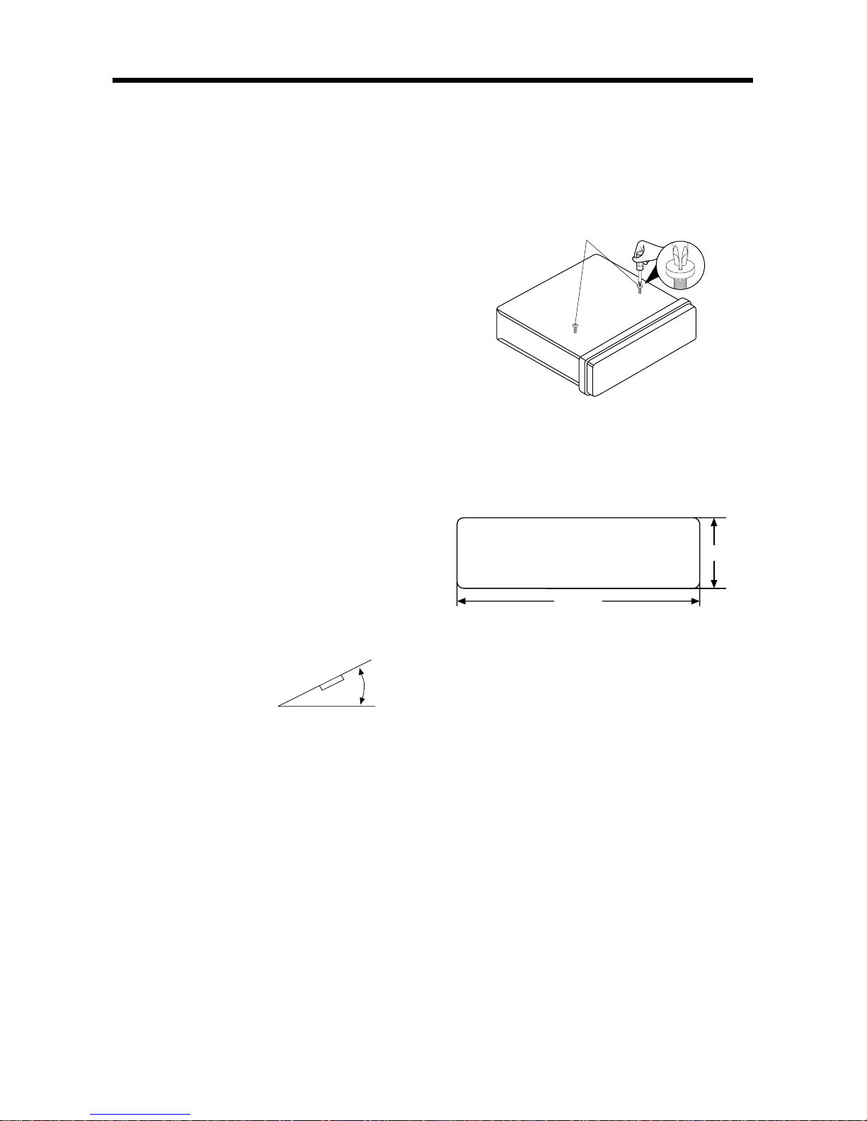
30˚
TAKE OUT SCREW BEFORE
INSTALLATION
Before install the unit, please remove the
two screws.
DIN FRONT-MOUNT (Method A)
Installation Opening
This unit can be installed in any dashboard
having an opening as show below:
Installing the unit
Be sure you test all connections first, and
then follow these steps to install the unit.
1. Make sure the ignition is turned off,
and then disconnect the cable from
the vehicle battery's negative (-)
terminal.
2. Disconnect the wire harness and the
antenna.
3. Press the release button on the front
panel and remove the control panel
(see the steps of “to detach the front
panel”).
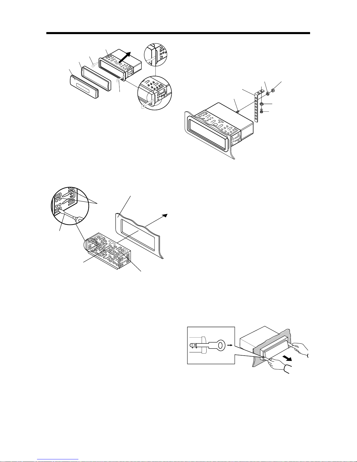
4. Lift the top of the outer trim ring then
pull it out to remove it.
5. The two supplied keys release tabs
inside the unit's sleeve so you can
remove it. Insert the keys as far as they
will go (with the notches facing up) into
the appropriate slots at the middle left
and right sides of the unit. Then slide
the sleeve off the back of the unit.
182 mm
53 mm
Take out screws before installation
INSTALLATION

6. Mount the sleeve by inserting the sleeve
into the opening of the dashboard and
bend open the tabs located around the
sleeve with a screwdriver. Not all tabs
will be able to make contact, so
examine which ones will be most
effective. Bending open the appropriate
tabs behind the dashboard to secure
the sleeve in place.
7. Reconnect the wire harness and the
antenna and be careful not to pinch
any wires or cables.
8. Slide the unit into the sleeve until it
locks into place.
9. To further secure the unit, use the
supplied metal strap to secure the back
of the unit in place. Use the supplied
hardware (Hex Nut (M5mm) and Spring
Washer) to attach one end of the strap
to the mounting bolt on the back of
the unit. If necessary, bend the metal
strap to fit your vehicle's mounting
area. Then use the supplied hardware
(Tapping Screw (5x25mm) and Plain
Washer) to attach the other end of
metal strap to a solid metal part of the
vehicle under the dashboard. This strap
also helps ensure proper electrical
grounding of the unit.
4
Front Panel
Outer Trim Ring
L Key
Sleeve
R Key
Sleeve
Dashboard
Screwdriver
Tabs
Note: to install the short threading terminal
of the mounting bolt to the back of the
unit and the other long threading terminal
to the dashboard.
10. Reconnect the cable to the vehicle
battery's negative (-) terminal. Then
replace the outer trim ring and install
the unit's front panel. (see the steps
of “to install the front panel”).
Removing the unit
1. Make sure the ignition is turned off,
then disconnect the cable from the
vehicle battery's negative (-) terminal.
2. Remove the metal strap attached the
back of the unit (if attached).
3. Press the release button to remove the
front panel.
4. Lift the top of the outer trim ring then
pull it out to remove it.
5. Insert both of the supplied keys into
the slots at the middle left and right
sides of the unit, then pull the unit out
of the dashboard.
Spring Washer
Tapping Screw
Plain Washer
Hex Nut
Metal Strap
Mounting Bolt
INSTALLATION

DIN REAR-MOUNT (Method B)
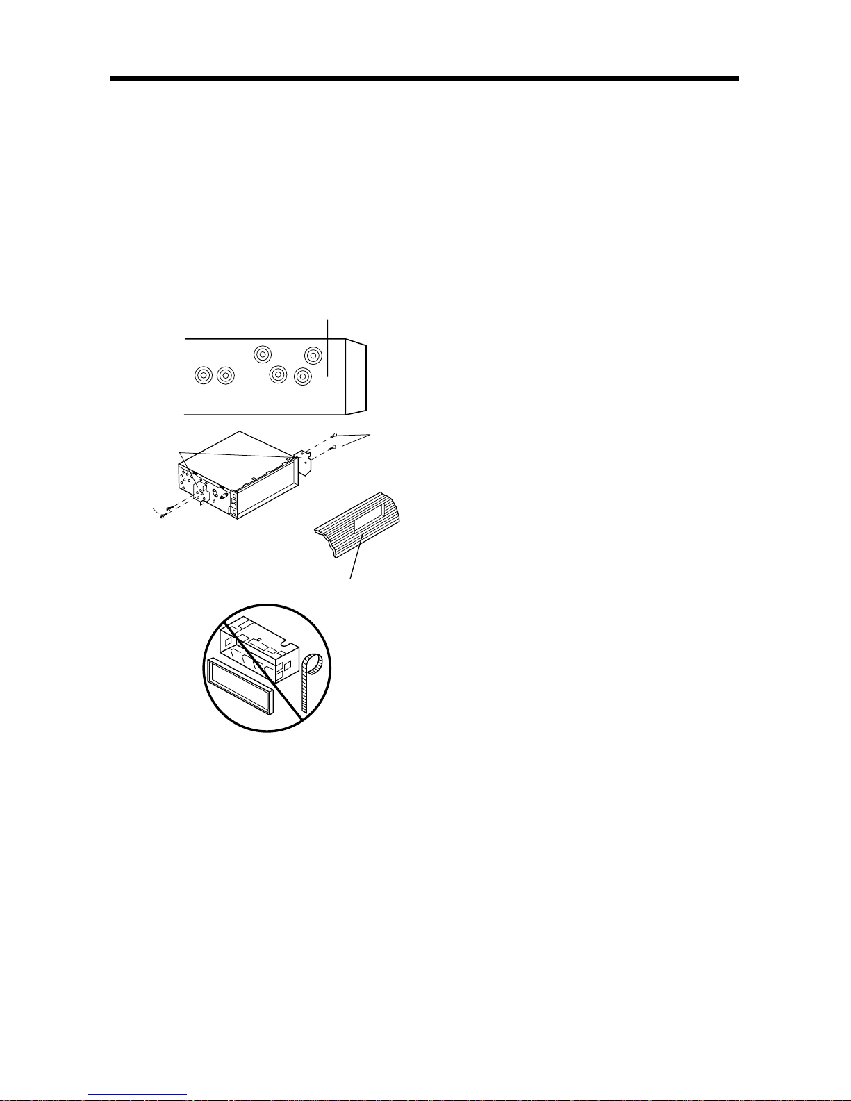
If your vehicle is a Nissan, Toyota, follow
these mounting instructions.
Use the screw holes marked T (Toyota),
N (Nissan) located on both sides of the
unit to fasten the unit to the factory radio
mounting brackets supplied with your
vehicle.
To fasten the unit to the factory radio
mounting brackets.
Align the screw holes on the bracket
with the screw holes on the unit, and
then tighten the screws (5x5mm) on
each side.
Note: the outer trim ring, sleeve and the
metal strap are not used for method B
installation.
5
Dashboard or
Console
Side view showing
Screw Holes marked
T, N
Factory Radio
Mounting
Bracket
Screw
Screw
INSTALLATION

6
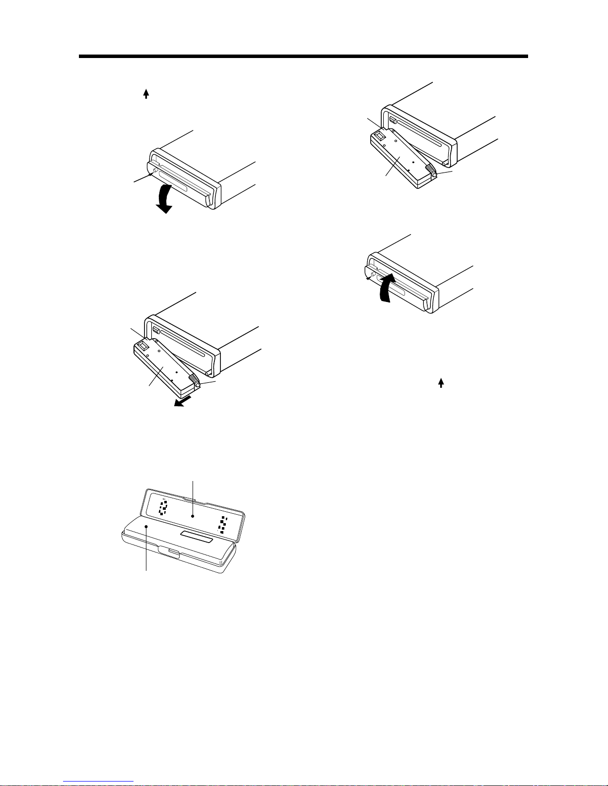
USING THE DETACHABLE FRONT PANEL
To Detach the Front Panel
1.Press the (open) button, then the
front panel will be folded down.
Open
2.To remove the front panel, lift it up at a
little angle from horizontal position,
then first pull out the right side and
then pull out the left side.
Front Panel
The left side
The right side
3.For safekeeping, store the front panel
in the supplied protective case
immediately after being removed.
Protective Case
Front Panel
To Install the Front Panel
1. To install the front panel, first insert the
left side into proper position then insert
the right side into place.
Front Panel
The left side
The right side
2.When the two sides fixed into place,
push the front panel into main unit.
3.Note that if the front panel fails to lock
in position properly, pressing control
button may not function and the
display may be missing some
segments. Press the (open) button
and then reinstall the front panel again.
Precautions when handling
1.Do not drop the front panel.
2.Do not put pressure on the display or
control buttons when detaching or re-
installing the front panel.
3.Do not touch the contacts on the front
panel or on the main unit body. It may
result in poor electrical contact.
4.If any dirt or foreign substances
adhered on the contacts, they can be
removed with a clean and dry cloth.
5.Do not expose the front panel to high
temperatures or direct sunlight in
anywhere.
6.Keep away any volatile agents (e.g.
benzene, thinner, or insecticides) from
touching the surface of the front panel.
7.Do not attempt to disassemble the
front panel.

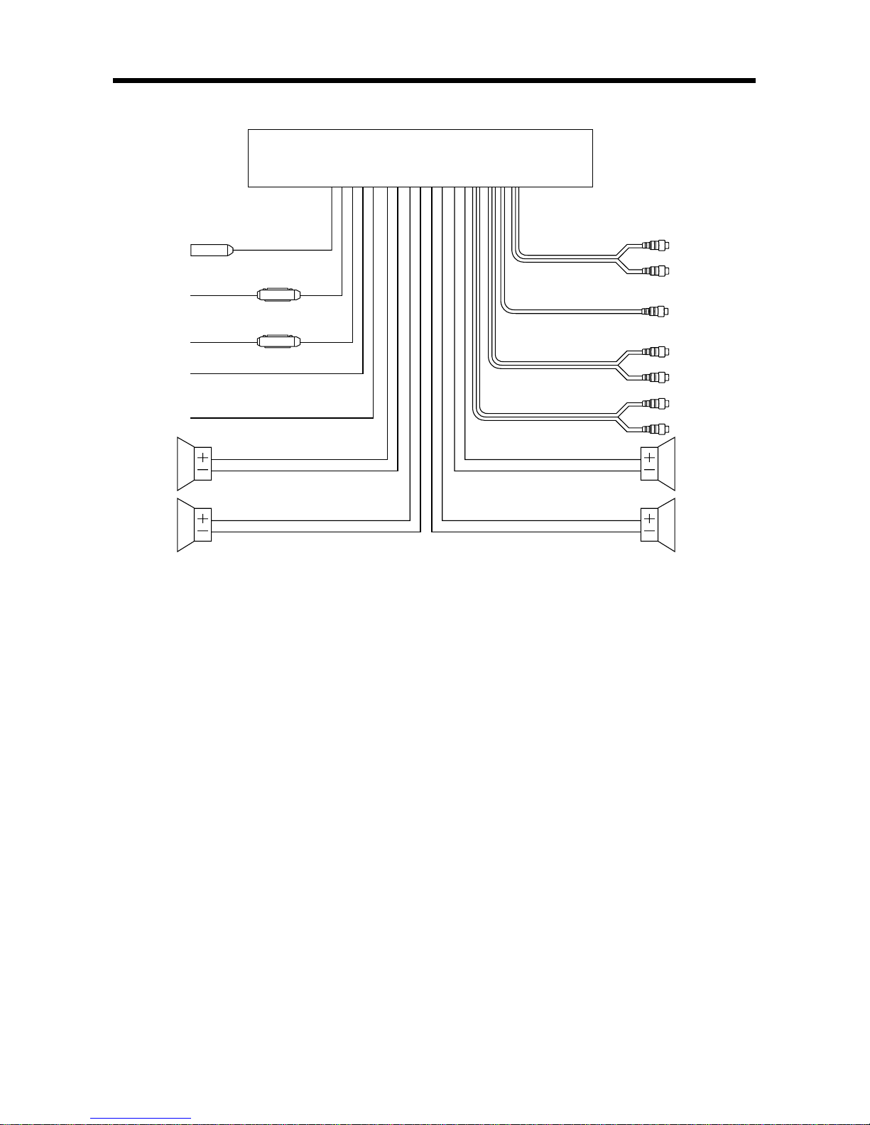
WIRING CONNECTION
7
FRONT Lch
SPEAKER
GREEN
GREEN/BLACK
MEMORY
BACK-UP (B+)
MAIN UNIT
Rch RED
Lch WHITE
AUX IN CABLE
IGNITION
SWITCH (ACC+)
POWER
ANTENNA
RED
GROUND (B–)
YELLOW
BLACK
BLUE REAR RCA CABLE
(BLACK)
ANTENNA CONNECTOR
(GREY) Rch RED
Lch WHITE
WHITE
WHITE/BLACK
REAR Lch
SPEAKER
SUBWOOFER CABLE (GREEN)
VIOLET
VIOLET/BLACK
GREY
GREY/BLACK
FRONT Lch
SPEAKER
REAR Rch
SPEAKER
FRONT RCA CABLE
(BROWN)
Rch RED
Lch WHITE
FUSE
FUSE

8
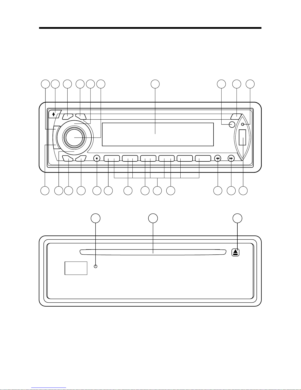
OPERATION
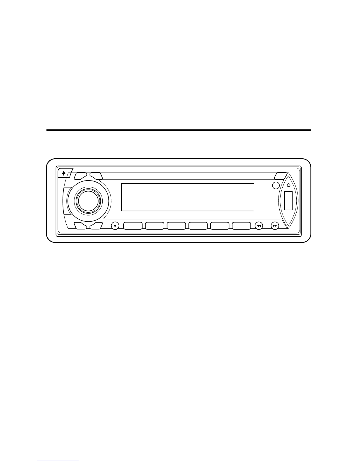
LOCATION OF KEYS
12 45
19 7 1 15 11 10 8 24 9 25
261716232221201318632 14
Indice
Lingue:
Altri manuali Insignia Ricevitore per auto

Insignia
Insignia IN-CS102 Manuale utente

Insignia
Insignia IN-CS102 Manuale utente

Insignia
Insignia 08-1623 Manuale utente

Insignia
Insignia IN-CS102 Manuale utente

Insignia
Insignia IN-CD101 Manuale utente

Insignia
Insignia NS-C3113 Guida rapida

Insignia
Insignia NS-C5112 Manuale utente

Insignia
Insignia NS-C3113 Guida rapida