Interflex IF15x Manuale utente

Installation and User Manual
Electronic Lock Cylinder IF15x

Copyright
Information in this documentation has been investigated and checked thoroughly in all
conscience. Nonetheless, errors cannot be excluded completely. Interflex Datensysteme
GmbH & Co. KG assumes no responsibility for the information in this manual, which is
subject to change without prior notice.
Interflex Datensysteme GmbH & Co. KG does not enter into any commitment.
Copyright © 2011
Printed on: 21.07.2011
Interflex Datensysteme GmbH & Co. KG
Ingersoll Rand Security Technologies
Zettachring 16
D-70567 Stuttgart
Germany
+49 (0711) 1322 0
Internet Email: info-interflex@eu.irco.com
Website: http://www.interflex.de
Ingersoll Rand’s Security Technologies Sector is a
leading global provider of products and services that
make environments safe, secure and productive. The
sector’s market-leading products include electronic
and biometric access control systems; time recording
and personnel scheduling systems; mechanical locks
and portable security; door closers and exit devices;
steel doors and frames; architectural hardware; and
technologies and services for global security markets.
Interflex is part of the Ingersoll Rand Security Technologies Sector.

Table of Contents i
Contents
Introduction 1
Short Description............................................................................................................................1
Scope of Delivery...........................................................................................................................2
Technical Data ...............................................................................................................................4
Installation/Dismantling 7
Installation of the Cylinder Body.....................................................................................................7
Installation of the Knob Module (with Disassembly Card)..............................................................7
Disassembly of the Knob Module (with Disassembly Card) ..........................................................8
Operation 9
Short-Time Release .......................................................................................................................9
Daily Release (Toggle Function)....................................................................................................9
Batteries 11
Battery Warning............................................................................................................................11
Low-Power Adapter......................................................................................................................13
Battery Change ............................................................................................................................14
Visual/Audible Signals 17
Index 21

1
Easy-to-install, highly flexible and yet safe – these are outstanding features of this state-of-
the-art electronic locking cylinder. With the IF15x series, you have purchased a cost-effective
and integratable solution.
Electronic identification media such as e. g. badges or easy-to-handle key tags are used as
"keys".
What else makes the Interflex locking cylinder second to none among its type: They
"communicate" with the access control systems IF6020 and IF6040. Utilize available
employee credentials and data stock from your access control systems. Conveniently
analyze the recorded data. Write complex settings to the locking cylinders in a convenient
way.
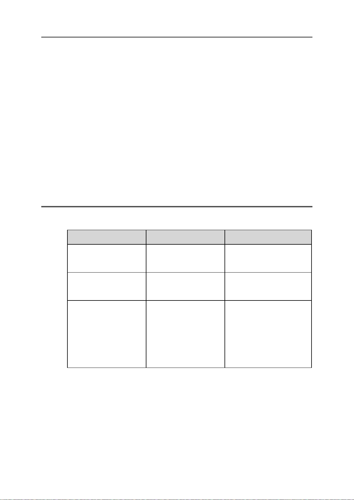
Short Description
IF 151 IF 152 IF 153
Double-knob locking
cylinder with one electronic
knob (brass, nickel-plated)
Double-knob locking
cylinder with two electronic
knobs (brass, nickel-plated)
Half cylinder with one
electronic knob (brass, nickel-
plated)
Standard length: 30/30mm
(lengths from 26/26 mm are
possible).
Standard length: 30/35mm
(lengths from 65 mm are
possible).
Standard length: 30/10mm.
The most important
components:
Electronic knob side
Mechanical knob side
Cylinder body
Fixing screw
Batteries
The most important
components:
Two electronic knob
sides
Cylinder body
Fixing screw
Batteries
The most important
components:
Electronic knob side
Cylinder body
Fixing screw
Batteries
C
HAPTER
1
Introduction

2 Introduction
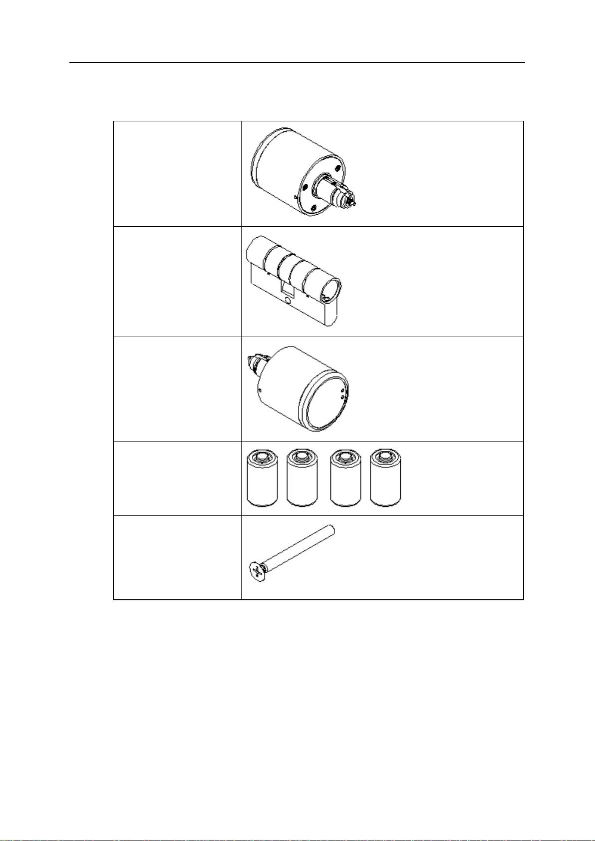
Scope of Delivery
Scope of Delivery IF151
Mechanical knob
Cylinder body
Knob module
Two batteries
Fixing screw
Introduction 3
Scope of Delivery IF152
Knob module
Cylinder body
Knob module
Four batteries:
Fixing screw

4 Introduction
Scope of Delivery IF153
Half cylinder body
Knob module
Two batteries
Fixing screw
Technical Data
Dimensions (in mm)
Cylinder Dimensions of the cylinder for Euro profile locks according to
DIN 18254
Electronic knob 40 × 41
Mechanical knob (only
IF 151) 29,5 × 20

Introduction 5
Power supply
Batteries Two lithium batteries per electronic knob, type CR2, 3 V
Battery life 10,000 actuations (approx.) at 20 °C, depending on the reader
type.
Storage life Four years (approx.)
Open when battery is
empty Possible at any time - external power source required (low-power
adapter).
Environmental conditions
Operating temperature 0 °C to 55 °C
Storage temperature -40 °C to 85 °C
Protection Category IP54 (IP standard, DIN EN 60529)
Installation location Indoor and outdoor areas (depending on product design). In the
event of use in outdoor areas, the general outdoor conditions must
be checked.
See also
Low-Power Adapter.......................................................................................13

Indice


