Iveco Motors V08 ENT M75 Manuale utente
VECTOR
V08 ENT M75
V08 ENT M11
V08 ENT M12
V 8 MODEL
DIESEL CYCLE
FOR MARINE APPLICATIONS
INSTALLATION DIRECTIVE
MAY 2006 EDITION
TECHNOLOGICAL EXCELLENCE

INSTALLATIONDIRECTIVE MAY 2006
2V08 ENT M75 -M11 -M12
We strongly recommend that you carefully read the indica-
tions contained in this document: compliance with them
protects the engine against irregular operation and assures
its reliability, safeguarding sea-going and maintenance person-
nel against accident hazards.
The indications contained in this directive pertain to the
V08 ENT M75 -M11 -M12 engines and complement the
IVECO MOTORS publication “Guide to the Installation of
Marine Engines”, the reader should refer to for anything that
is not explained herein.
For more complete information about the engine, please
refer to the appropriate technical brochure.
Use of fuels and oils with different characteristics from
those set out in the operation and maintenance manual may
compromise the regular operation of the engine, limiting its
performance, reliability and working life.
Exclusive use of IVECO Original Parts is a necessary condi-
tion to maintain the engine in its original integrity.
Tampering, making modifications and using non original parts
can jeopardize the safety of boat engineers and users.
To obtain spare parts, you must indicate:
- Commercial code, serial number and indications shown
on the engine tag;
- Part number of the spare as per spare part catalog.
The information provided below refer to engine charac-
teristics that are current as of the publication date. IVECO
MOTORS reserves the right to make modifications at any
time and without advance notice, to meet technical or
commercial requirements or to comply with local legal and
regulatory requirements.
We refuse all liability for any errors and omissions.
The reader is reminded that the IVECO MOTORS Technical
Assistance Network is always at the Customer’s side with its
competence and professionalism.
Publication IVECO MOTORS edited by:
IVECO PowerTrain
Advertising & Promotion
Pregnana Milanese (MI)
www.ivecomotors.com
Printed P3D64V001 E - May 2006 Edition
FOREWORD

INSTALLATIONDIRECTIVE 3
V08 ENT M75 -M11 -M12
MAY 2006
Page
CONTENTS
Indications for consultation
The different versions of the motors are generally shown
using the same pictures and descriptions, however important
differences are shown separately.
1. WARNINGS AND CAUTIONS 4
2. ENGINE PARTS AND COMPONENTS 6
3. INSTALLATION OVERVIEW 10
4. GENERAL INSTALLATION CRITERIA 11
5. TECHNICAL DATA FOR INSTALLATION 12
6. IDENTIFICATION DATA 14
7. FUEL LINE 15
8. ELECTRICAL EQUIPMENT 17
9. MAIN ANALOG INSTRUMENT PANEL 26
10. SECONDARY ANALOG INSTRUMENT PANEL 30
11. DRILLING PLANS FOR ANALOG PANELS 31
12. CUSTOMIZED INSTRUMENT PANEL 32
13. SENSORS FOR DETECTION
AND INSTRUMENT PANEL SIGNALLING 34
14. PREPARING THE ENGINE FOR FIRST START-UP 37
15. TESTS BEFORE THE FIRST START-UP 37
16. FIRST ENGINE START 38
17. EDC ECU INDICATION LIGHTS 40
18. UNDERWAY CHECKS 43
19. PREPARING THE ENGINE
FOR LONG IDLE PERIODS 44
20. ELECTRIC DIAGRAMS 46
21. APPENDIX 53

INSTALLATIONDIRECTIVE MAY 2006
4V08 ENT M75 -M11 -M12
To obtain the best engine performance, it is essential not to
deviate from the mission profile for which it was produced
and set up.The engine must not be used for purposes other
than those stated by the manufacturer. IVECO MOTORS is
willing to examine any need for particular installations befo-
rehand. Use of an electronically controlled injection system,
in providing the engine with performance benefits, requires
that the installer and maintenance specialist comply with
some fundamental rules, which will become more and more
commonplace as use of such equipment becomes progressi-
vely more widespread. Boat outfitters and maintenance spe-
cialists are invited to closely follow the instructions contained
herein. No modifications to the engine, its accessories and
components, are allowed.
Failure to comply with the instructions that follow shall
void the warranty and relieve IVECO MOTORS of all
liabilities.
For personnel safety
Specialists and installers are cautioned to comply with
workplace safety rules and to adopt prescribed individual
protection devices when working.
oDrain the cooling, lubrication and fuel lines only after
the fluids have duly cooled. The pressurized cap of the
coolant line may be opened only after the engine has
duly cooled.
oBatteries contain a highly corrosive sulphuric acid solu-
tion: must never be upset and must be handled with
the utmost caution to prevent spillage. Ensure that the
battery compartment is adequately ventilated.
Handling
The engine must be handled by experienced personnel,
using the prescribed tool or a rocker arm that keeps the
lifting lines parallel and with adequate equipment in terms
of capacity and size.The two eyebolts provided for lifting the
engine alone must always be used simultaneously.
Installation
oKnife switches or battery breakers may be used on the
power supply line of the engine electronic unit, provided
they are not used to shut off the engine.
oDo not modify the wiring harnesses; their length may
not be modified: use only available extensions.
oDo not use electronic device wiring harnesses not com-
pliant with the IVECO MOTORS directive, in terms of
length, type of conductor, location, clamping, connection
of the shielding and earth braids.
oTo avoid any interference, the wiring harnesses of the
different on-board electronic devices must follow diffe-
rent paths from those of the engine electronic systems.
oDo not connect any extraneous user device to the engi-
ne electrical equipment.
oDo not energize the on-board electrical system of the
boat without first verifying that there are no short cir-
cuits.
oDo not branch pipes off to draw fuel from the engine
supply lines.
oDo not make any change to the engine’s hydraulic circui-
ts and components.
oDo not execute arc welding operations before removing
the electronic units from their seating, placing them at an
adequate safety distance.
oDo not subject electronic units to temperatures excee-
ding 80°C.
oDo not paint electrical components and their connec-
tions.
oDo not alter the data contained in the engine control
electronic unit.
oComply with prescribed procedures and torque values
when tightening threaded elements.
Start-up
oReady the engine following the procedure set out in
Chapter 14.
oWhen starting the engine the first time, have suitable
means available to cut off air intake in case of a runaway
condition.
oStart the engine after ensuring that it is complete with
every part specified by the manufacturer and required
by the installation, without attempting to start it with
caps and occlusions to the lubrication, cooling and fuel
feed lines.
oCheck that the fluid lines are perfectly sealed, especially
lines for fuels and lubricants, which may cause fires and
consequent harm to persons and equipment.
oMake sure that the various pipelines are not in contact
with warm surfaces or moving parts.
oThe installing yard is required to carry out tests to
verify the functional compatibility between the electri-
cal-electronic equipment of the engine and the other
electronic equipment present on the boat.
Tests and tuning up
oNever disconnect the batteries when the engine is run-
ning.
oRemove the electrical connections from the batteries
before any operation on the electrical system.
oEnsure that the battery terminals comply with the exact
polarity, are properly tightened and protected against
accidental short circuits and corrosion phenomena.
1. WARNINGS AND CAUTIONS

INSTALLATIONDIRECTIVEMAY 2006 5
V08 ENT M75 -M11 -M12
oDo not connect or disconnect electrical connections
when electrical power supply is on.
oDo not cause sparks in the attempt to verify the presen-
ce of electrical voltage.
oDo not draw fuel through unfiltered lines.
oDo not clean the engine and its parts with corrosive or
abrasive detergent substances, to avoid compromising
the integrity of electrical connections.
oThe engine fluids and air, coolant, and oil filters discar-
ded after use must be properly stored and delivered to
appropriate collection centres.
Long engine inactivity periods
Before long periods of inactivity, ready the engine following
the procedure set out in Chapter 19.

INSTALLATIONDIRECTIVE
6V08 ENT M75 -M11 -M12 MAY 2006
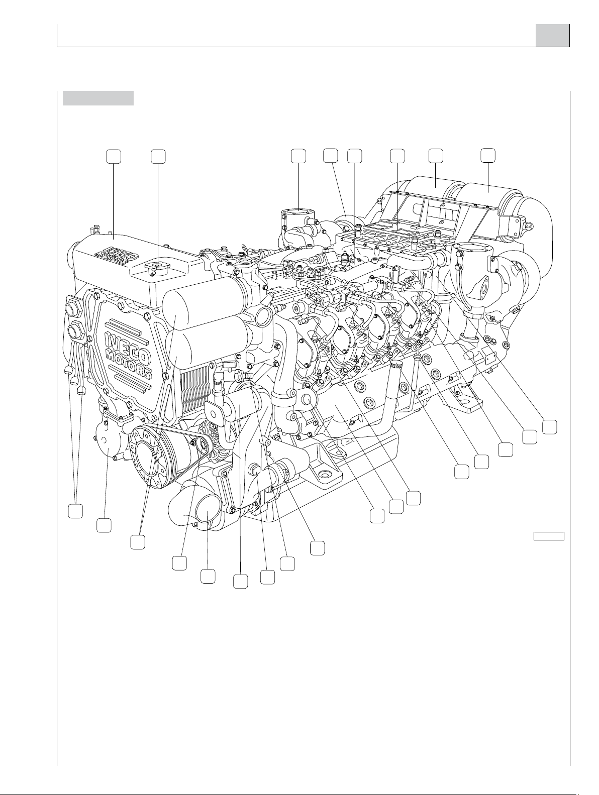
2. ENGINE PARTS AND COMPONENTS
Figure 1A
05_001_V
9
4
12
10
3
112
11
8
14
15
13
5 6 7
18
16
17
1. Intake air filter - 2. EDC Electronic Central Unit - 3. Common rail high pressure injection pump - 4. Cooled turbo-charger -
5. Exhaust gas outlet - 6. Lever for switching fuel filters - 7. Engine coolant level sensor - 8. Water/water heat exchanger -
9. Pressurization cap for coolant tank - 10. Sea water pump - 11. Engine coolant pump - 12. Fuel filters - 13. Lifting padeyes -
14. Cylinder 1 electro-injector - 15. Cooled exhaust manifold - 16. Cylinder 4 electro-injector - 17. Lifting padeyes -
18. Air-sea water heat exchanger.
INSTALLATIONDIRECTIVE 7
V08 ENT M75 -M11 -M12
MAY 2006
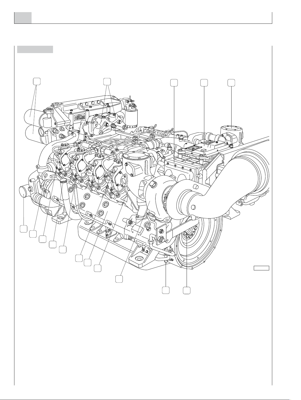
Figure 1B
05_008_V
9
15
13
10
11
16
20
7
127
3 6
12
8
14
5
4
17
19
23
22
21
24
18
1. Engine coolant tank - 2. Pressurization cap for coolant tank - 3. Exhaust gas outlet - 4. Cooled turbo-charger - 5. Common rail high
pressure injection pump - 6. EDC Electronic Central Unit - 7. Intake air filter - 8. Air-sea water heat exchanger - 9. Lifting padeyes -
10. Cylinder 8 electro-injector - 11. Lubricating oil dipstick - 12. Lubricating oil refill cap - 13. Cylinder 5 electro-injector - 14. Cooled
exhaust manifold - 15. Lifting padeyes - 16. Location of the low pressure fuel transfer pump - 17.Tap and fitting for lubricating oil
transfer - 18. Sacrificial anode - 19. Lubrication oil transfer electrical pump - 20. Sea water intake - 21. Alternator - 22. Lubricating
oil filters - 23. Engine coolant pump - 24. Electrical equipment wiring connectors.
INSTALLATIONDIRECTIVE
8V08 ENT M75 -M11 -M12 MAY 2006
05_002_V
3
6
14
9
15
11
13
12
7
54
12
8
16
10
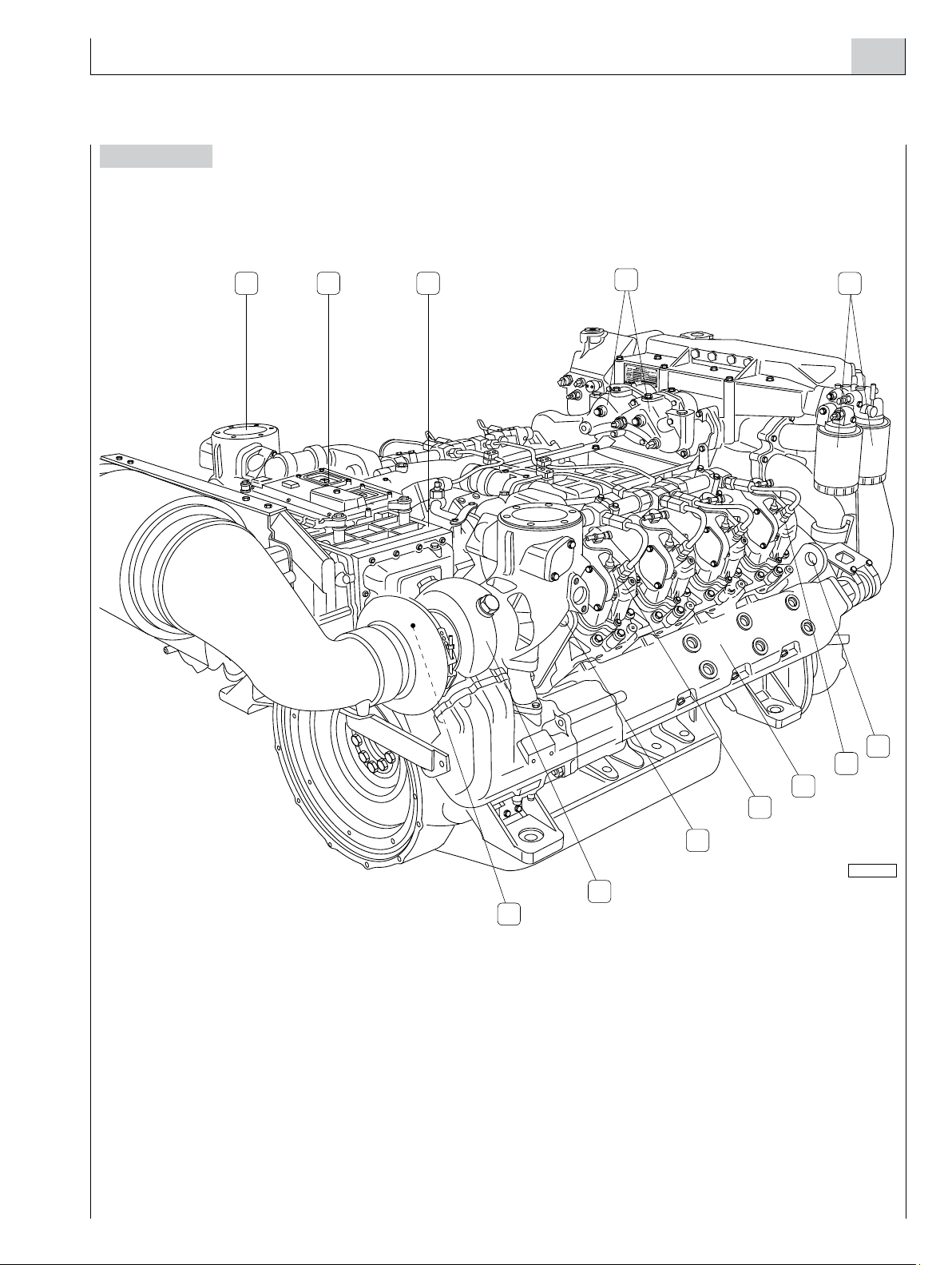
Figure 2A
1. Lubricating oil filters - 2. Location of thermostatic valves - 3. Air-sea water heat exchanger - 4. EDC Electronic Central Unit -
5. Exhaust gas outlet - 6. Fuel inlet and outlet fittings - 7. Crankshaft sensor - 8. Cooled turbo-charger - 9. Lifting padeyes -
10. Cooled exhaust manifold - 11. Cylinder 8 electro-injector - 12. Lubricating oil dipstick - 13. Lubricating oil refill cap -
14. Cylinder 5 electro-injector - 15. Lifting padeyes - 16. Sea water intake.
INSTALLATIONDIRECTIVE 9
V08 ENT M75 -M11 -M12
MAY 2006
05_009_V
5
1
7
11
10
8
9
6
32 4
12
Figure 2B
1. Exhaust gas outlet - 2. EDC Electronic Central Unit - 3. Air-sea water heat exchanger - 4. Location of thermostatic valves -
5. Fuel filters - 6. Lifting padeyes - 7. Cylinder 1 electro-injector - 8. Cooled exhaust manifold - 9. Cylinder 4 electro-injector -
10. Lifting padeyes - 11. Cooled turbo-charger - 12. Sacrificial anode (placed on the air/water heat exchanger).
INSTALLATIONDIRECTIVE MAY 2006
10 V08 ENT M75 -M11 -M12
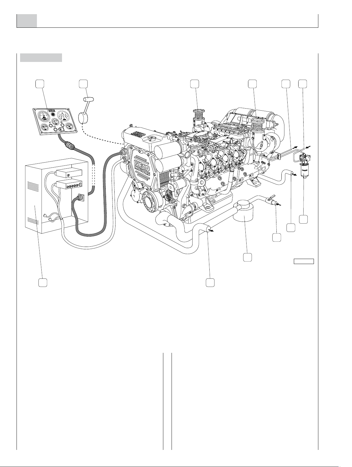
3. INSTALLATION OVERVIEW
Figure 3
The figure shows the set of components of an installation,
including those supplied with the engine equipment, standard
or optional, and those supplied or produced by the yard.
It provides a comprehensive picture of the operations
required to install the engine.
Components arrangement and illustrations are not binding
but merely indicative, subject to the choices made by yard
engineers according to their skills, available spaces and the
prescriptions set out herein.
05_003_V
1 2 3 4 5
6
7
8
9
1011
3
1. Main instrument panel - 2.Throttle actuator - 3. Exhaust gas outlet - 4. Fuel return pipe to tank - 5. Fuel suction pipe -
6. Prefilter with priming pump - 7. Sea water outlet from air/water heat exchanger - 8.To the filtered sea water intake -
9. Sea water decanter filter - 10. Sea water outlet from water/water heat exchanger - 11. Electrical system cabinet.
Questo manuale è adatto per i seguenti modelli
4
Indice
Altri manuali Iveco Motors Motore


