JCF Audio DA8-V Manuale utente
DA8-V USER MANUAL
JCF AUDIO, LLC.
11247 CAMARILLO ST.
NORTH HOLLYWOOD, CA 91602
WWW.JCFAUDIO.COM
J C F A U D I O
D A 8 - V
11 2 4 7 C a m a r i l l o S t . N . H o l l y w o o d , C A 9 1 6 0 2 • w w w. j c f a u d i o . c o m

DA8-V
Safety Information
Do not repair, modify, service this device except in the manner in which it is described
in this manual. Doing so can endanger the user and others as well as void the warranty.
Fuses should be replaced with the exact values and sizes stated in the manual.
JCF Audio, LLC accepts no responsibility for legal actions or for direct, incidental, or
consequential damages that may result from improper installation, configuration, or use
of the DA8-V.
Warnings:
Lethal potential present inside DA8-V and Power supplies
even without power applied.
Do not connect power supplies to wall without connections
to DA8-V main unit secure.
Do not remove any lids with power applied.
DA8-V must be earthed to provide compliance with most
electrical codes.
JCF Audio
J C F A u d i o!D A 8 - V
1

Overview
The DA8-V is an 8 channel Digital to Analog converter that utilizes the AKM AK4359 in combi-
nation with a tube line stage that was inspired by the Ampex 351 reproduce circuitry.
The unit accepts the industry standard AES/EBU protocol on a DB25 connector with an addi-
tional courtesy turn-around. The AES/EBU DB25’s follow the most commonly used “triangle”
or Tascam® pinout. The AES/EBU inputs operate in single-wire mode exclusively at all sam-
pling frequencies. The DA8-V derives its sync source from the incoming AES/EBU stream un-
der all conditions.
The DA8-V has two analog outputs each coming from two separate, floating sources (with fac-
tory configuration). This can aid in installations where the outputs of the DA8-V must be con-
nected to multiple devices.
0 dBu is referenced to 0.775 vrms for this manual
Front Panel Controls
Level Adujstments - These level adjustments for the output of the device. The fully clock
wise position provides no attenuation and the fully counter-clockwise position provides ap-
proximately 20 db of attenuation. Calibration level details are listed in the Specifications sec-
tion.
Receiver Error - This LED indicates that the AES/EBU input signal to the unit is invalid.
Operation - This switch must be in the X1 / X2 position for operation up to and including
96kHz. The switch must be in the X4 position for operation @ 176.4kHz and 192kHz.
Reset - This switch resets the digital section of the device.
JCF Audio
J C F A u d i o!D A 8 - V
2
Rear Panel
Analog Power - This 4 pin XLR jack is for connection to the supplied analog power supply.
The pinout is as follows:
Pin 1 -
Pin 2 -
Pin 3 - B-
Pin 4 - B+
Digital Power - This 4 pin connector is for connection to the supplied digital power supply.
The pinout is as follows:
Pin 1 -
Pin 2 -
Pin 3 -
Pin 4 -
JCF Audio
J C F A u d i o!D A 8 - V
3
}
6 VAC 4.8A
}~300 VDC 0.125A idle
}
~10 VAC
}~10 VAC
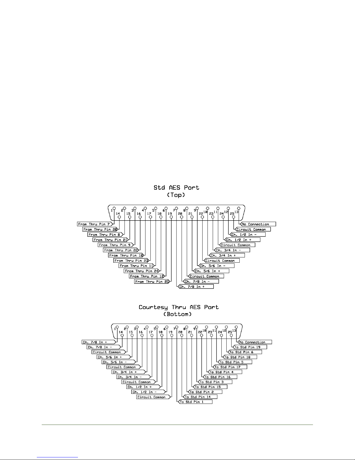
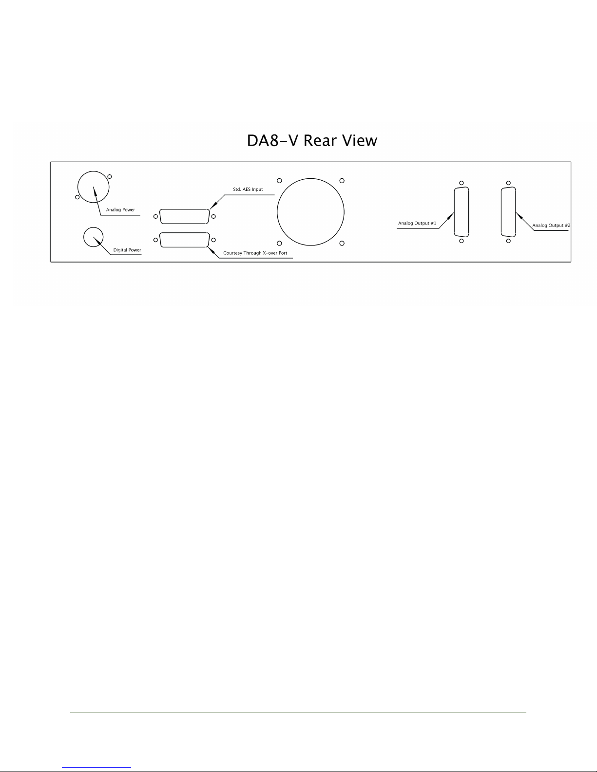
AES/EBU Input -
!The popularity of DB25 for bi-directional AES/EBU communication presents a
unique challenge to the user attempting to connect devices to a system that only utilize
one direction (as in the case of the DA8-V). The most common situation is that one will
go to plug in the converter for the first time and find that their DAW already has some-
thing connected to it’s AES/EBU DB25 port. Since AES/EBU is, for the most part, a
single source/single load system, a likely scenario would be that the user is using
what’s there already to get information from an A/D converter or other digital devices
into their DAW. In these cases we have offered the following solution:
!The top DB25 port is the Standard Input port (see photo above). The included
AES/EBU cable can connect any Tascam® AES/EBU port to the DA8-V’s top port. The
bottom port is a Courtesy Thru port that can take the previously existing cabling to
other devices if necessary.
JCF Audio
J C F A u d i o!D A 8 - V
4
!The AES/EBU input is self-syncing and the Ch. 1/2 input stream’s recovered
clock is the reference for the unit under all conditions. This allows for setup-and-forget
operation on all sampling rates up to and including 96kHz. The front panel control la-
beled “Operation” must be set to X4 for use at 176.4kHz, 192kHz and surrounding vari-
speed variants. Channels 3, 4, 5, 6, 7, and 8 may not be used without a valid AES/EBU
stream on Ch. 1/2.
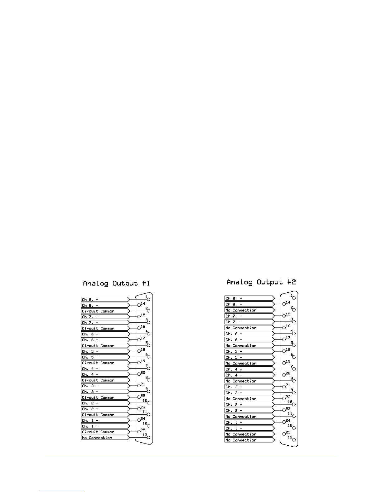
Analog Outputs -
!There are two analog output connectors present on the rear panel. As the unit is
factory configured, each output is galvanically separate and fully floating. Analog Out-
put #1 is closest to the fan. (See DA8-V Rear View picture)
!Analog Output #1 has circuit common connections on each channel. Analog
Output #2 does not. The latter is useful in cases where a “pin 1 lift” is required across
all 8 output channels.
!There is an internal option to strap the output transformer in series which will
provide an additional 6db of output level and a commensurate increase in output im-
pedance. In this case the output connectors are in parallel, each coming from the series-
connected transformer secondary. Regardless of output strapping, the presence of cir-
cuit common-per-connector is unchanged. (See below picture)
JCF Audio
J C F A u d i o!D A 8 - V
5

Fan - The fan hole in the rear of the unit and the air inlet grate at the front of the unit
should remain unobstructed at all times. Proper airflow is essential to keep the tubes
and surrounding circuitry at a reasonable operating temperature. Do not defeat the fan
for any reason.
Power Supplies:
!Both Analog and Digital power supplies should be kept away from the main unit
and their chassises should not touch each other, the DA8-V nor any other object . Both
units should rest on their rubber feet at all times. The analog supply’s fan ports should
be completely unobstructed and away from objects that generate and/or are susceptible
to heat. Proper airflow is important to keep the rectifier tube cool and functioning for
its expected tube life. Do not defeat the fans for any reason.
!The rectifier tube included with the analog power supply is shipped wrapped in
bubble wrap inside the supply enclosure itself. The bottom 6 screws should be re-
moved, the bubble wrap discarded, and the tube inserted in its socket. The bottom
plate should then be replaced and all 6 screws refitted. Do not perform this operation
with power applied.
!The power supplies should never be connected to the wall without
all their lids secure and connections to the DA8-V made first. Failure to
do so can result in serious injury.
JCF Audio
J C F A u d i o!D A 8 - V
6
Cabling:
The DA8-V ships with 3 included cables:
!A male to male 4-pin cable for transferring power from the included analog
power supply to the main unit. This cable is wired “straight through”. Pin 1 to Pin 1,
etc.
!A female to female circular “ham connector” cable for transferring power from
the included digital power supply to the main unit. This cable is wired “straight
through”. Pin 1 to Pin 1, etc.
!A 5’ standard AES to AES db25 crossover cable. This cable is for transferring
Tascam® compatible pinned AES/EBU signals to and through the main unit.
Specifications
D/A Calibration Range - (w/ factory split parallel output)
MIN
MAX
Level fully counterclockwise
Level fully clockwise
0dBfs = +4.8dBu at outputs
0dBfs = +24.8dBu at outputs
-0.8dBfs = +4dBu at outputs
-20.8dBfs = +4dBu at outputs
-18dBFS = -13.2 dBu at outputs
-18dBFS = +6.8 dBu at outputs
D/A Calibration Range - (w/ series outputs)
MIN
MAX
Level fully counterclockwise
Level fully clockwise
0dBfs = +10.8dBu at outputs
0dBfs = +30.8.dBu at outputs
-6.8dBfs = +4dBu at outputs
-26.8dBfs = +4dBu at outputs
-18dBFS = -7.2 dBu at outputs
-18dBFS = +12.8 dBu at outputs
JCF Audio
J C F A u d i o!D A 8 - V
7

De-emphasis is not supported anywhere in the DA8-V.
Power Consumption:
!100W Idle
Tube Compliment:
!8 - 12AX7
!8 - 12AU7
!1 - 5R4 (Located in Analog Power Supply) Life Expectancy is ~18 months !!
!!on this tube.
THD+N
!(48kHz, 400 to 18k BW, 1kHz tone)
! ! -20dBFS to 0 out: 0.03%
!!-10dBFS to +10 out: 0.008%
!!-30dBFS to -10 out: 0.1%
!!-35dBFS to -10 out: 0.15%!
!(192kHz, 400 to 18k BW, 1kHz tone)
! ! -20dBFS to 0 out: 0.03%
!!-10dBFS to +10 out: 0.03%
!!-30dBFS to -10 out: 0.08%
!!-35dBFS to -10 out: 0.15%
!(192kHz, 10 to 200k BW, 1kHz tone)
! ! -20dBFS to 0 out: 0.057%
!!-10dBFS to +10 out: 0.035%
!!-30dBFS to -10 out: 0.18%
!!-35dBFS to -10 out: 0.3%
JCF Audio
J C F A u d i o!D A 8 - V
8

Frequency Response (No output load)
!@ 44.1kHz: 20Hz to 20kHz +/- 1.5dB
!@ 88.2kHz: 20Hz to 40kHz +/- 1.5dB
!@ 176.4kHz: 20Hz to 80kHz +/- 1.5dB
DAC residual noise (No BW limiting, No attenuation)
!192k: - < -51dBu
!96k: - < -51dBu
!48k: - < -51dBu
DAC residual noise (22k upper BW limit, “Lev” fully clockwise)
!192k: -71dBu
!96k: -70dBu
!48k: -65dBu
Shipping weight
!67 lbs. 30”X 24”X10”
Max Dimensions
!L: 14.5”
!W: 19”
!H: 3.5”
JCF Audio
J C F A u d i o!D A 8 - V
9
Indice
Altri manuali JCF Audio Convertitore multimediale


