Table of Contents
OPL Control Door Assembly
For Models Mfd. as of July 1, 2002.................................................................................................. 2
OPL Control Door Assembly
For Models Mfd. prior to July 1, 2002.............................................................................................. 3
Phase 7 OPL Microprocessor Control Panel Assembly ........................................................................... 4
Phase 7 OPL Microprocessor Control Box Assembly ............................................................................. 5
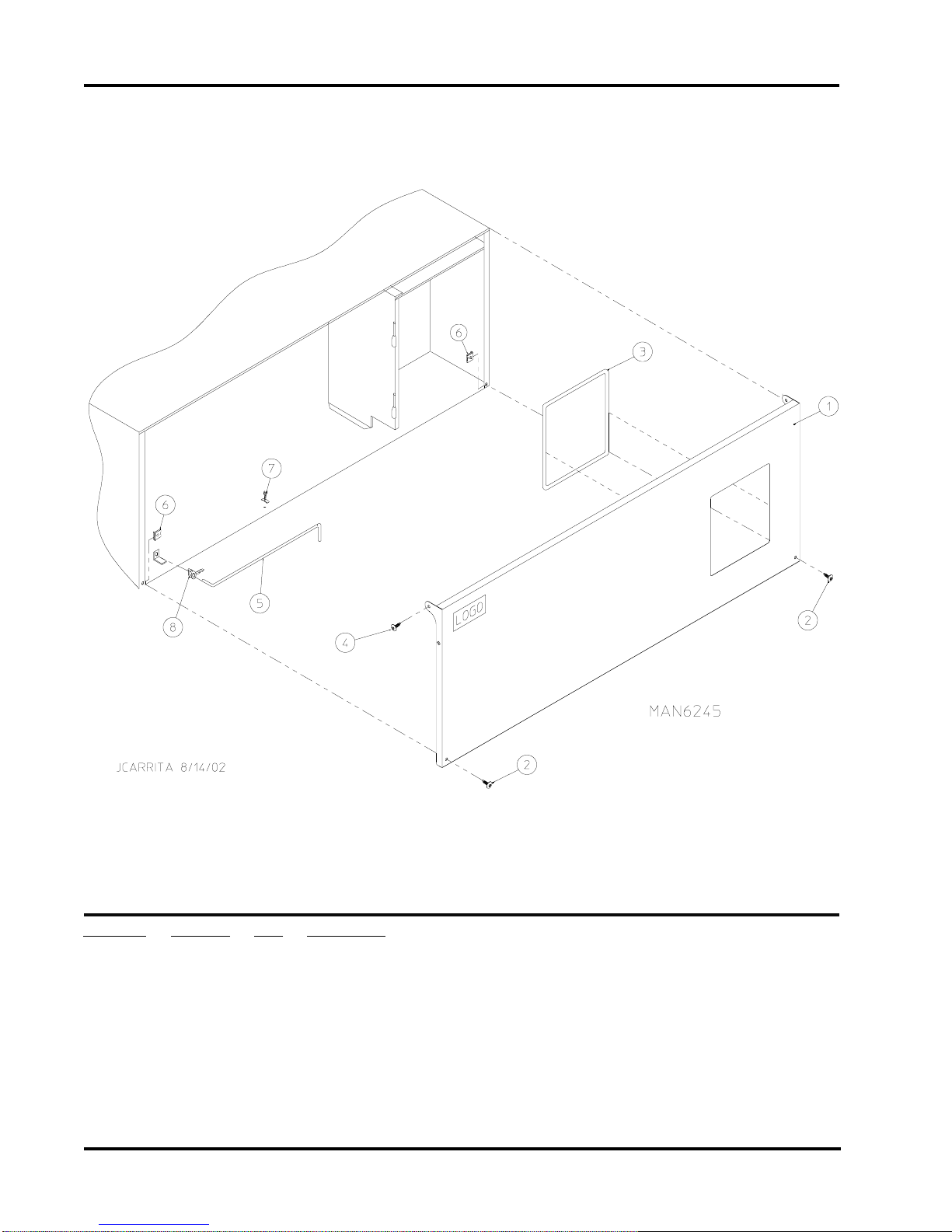
Front Panel Assembly
For Models Mfd. as of July 1, 2002.................................................................................................. 6
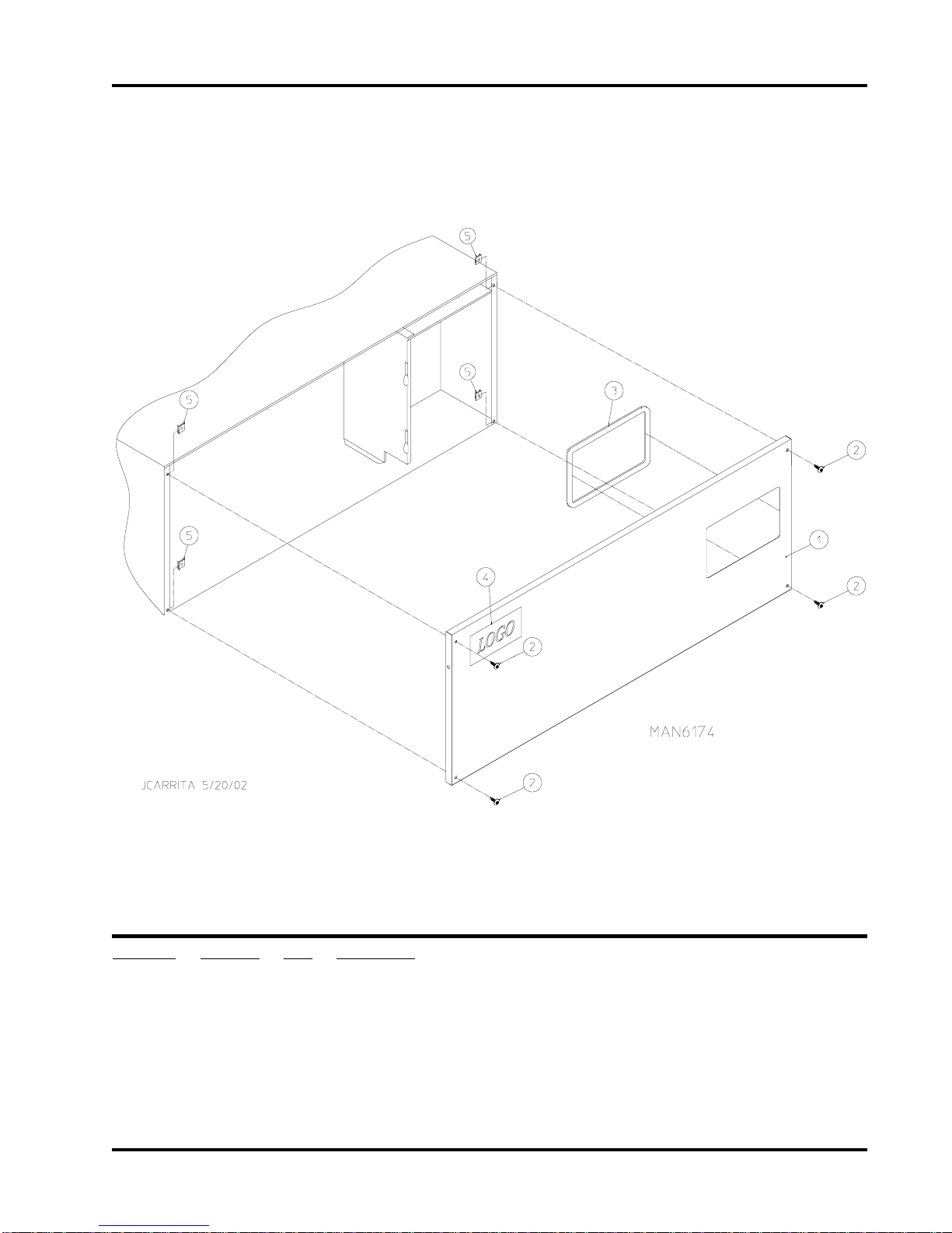
Front Panel Assembly
For Models Mfd. prior to July 1, 2002.............................................................................................. 7
Main Door “Steel” Assembly .................................................................................................................. 8
Main Door Switch Assembly................................................................................................................... 9
Basket (Tumbler)/Support Assemblies ................................................................................................... 10
Drop Lint Door Assembly
For Models Mfd. as of July 1, 2002.................................................................................................11
Lint Trap Assembly
For Models Mfd. as of July 1, 2002................................................................................................ 12
Lint Drawer/Lint Drawer Switch Assembly
For Models Mfd. prior to July 1, 2002............................................................................................ 13
Idler Bearing Assembly ......................................................................................................................... 14
Basket (Tumbler) Bearing Assembly ...................................................................................................... 15
Motor Mount Assembly .................................................................................................................. 16, 17
Sensor Bracket Assemblies
For Models Mfd. as of July 1, 2002.......................................................................................... 18, 19
Sensor Bracket Assemblies
For Models Mfd. prior to July 1, 2002...................................................................................... 20, 21
Direct Spark Ignition (DSI) Burner Assembly .................................................................................. 22, 23
Hot Surface Ignition (HSI) Gas Burner Assembly ............................................................................ 24, 25
Electric Oven Assembly .................................................................................................................. 26, 27
Rear Electric Relay Panel Assembly ................................................................................................ 28, 29
S.A.F.E. Temperature Probe Assembly ................................................................................................. 30
S.A.F.E. Solenoid and Piping Assembly ................................................................................................ 31
Steam Coil/Air-Operated Steam Damper Assembly ........................................................................ 32, 33
Outer Top/Back Guard Assemblies ....................................................................................................... 34
Electrical Oven Component Application Chart ....................................................................................... 35
Additional Parts Available ..................................................................................................................... 36