Jonsered SM 2055 E Manuale utente

Operator’s Manual
Please read these instructions carefully
and make sure you understand them
before using the one-man sawmill.
SM 2186
SM 2055 E

2– English
TABLE OF CONTENTS
Introduction ....................................... 3
Symbols ............................................. 4
Warning Signs ................................... 4
Safety Regulations ............................ 5
Description ........................................ 7
Installation ....................................... 16
Fuel Handling .................................. 21
Starting and Stopping..................... 23
Use.................................................... 25
Maintenance .................................... 29
Technical Data ................................. 33

English –3
Introduction
This operator’s manual describes in detail how the
one-man sawmill is used and maintained and how
servicing is to be carried out. It also describes the
measures to be taken for maximum safety and how the
safety features are designed and function, as well as
how they are inspected, maintained, and repaired if
necessary.
NOTE! The section dealing with safety must be
read and understood by all those who install, use,
or repair the sawmill.
The operator’s manual comprises installation, usage,
and the different maintenance procedures that can be
performed by the operator. More comprehensive
servicing or troubleshooting should be performed by
the dealer’s service personnel.
The operator’s manual describes all the requisite
safety features and should be read and understood by
the user before the sawmill is assembled.
Symbols and warning signs shown on the next page
can be found in this operator’s manual and on the one-
man sawmill. If a decal on the sawmill has been
damaged or is worn, a new warning decal must be
applied as soon as possible in order to ensure the
greatest possible safety when using the sawmill.
The one-man sawmill shall only be used to cut boards
and planks from logs.
The one-man sawmill should be used outdoors and
not in enclosed spaces.
INTRODUCTION

4–English
KEY TO SYMBOLS
Symbols
The symbols below are used in this operator’s manual.
Warning Signs
The decal with the symbols below is found on the one-
man sawmill.
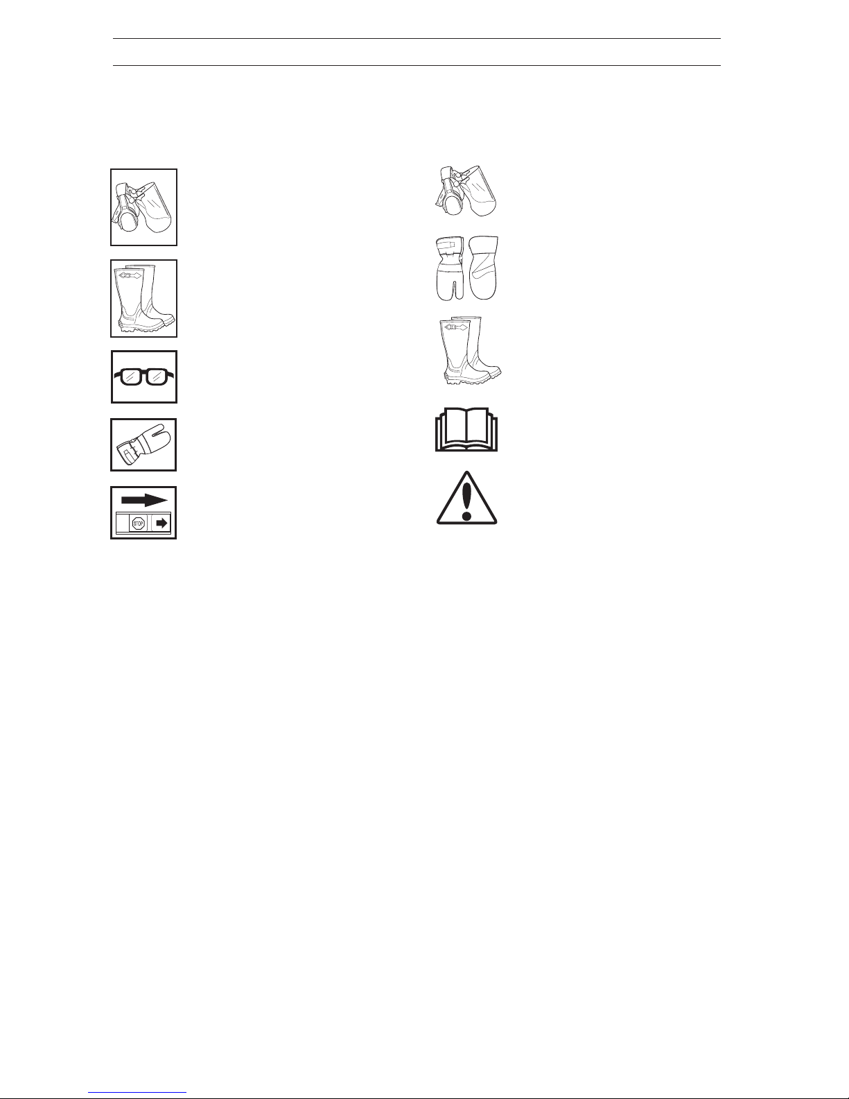
Boots or work shoes with steel
toecaps and non-slip soles
should be worn.
Eye protection and hearing
protection should be used.
Read this manual carefully and
make sure you understand it
before attempting to use the one-
man sawmill.
Exercise caution.
Protective gloves should be worn.
Eye protection and hearing
protection should be used.
Boots or work shoes with
steel toecaps and non-slip soles
should
be worn.
Eye protection should be used.
Protective gloves should be
worn.
Switch off the engine by moving
the stop switch to the STOP
position before carrying out any
checks or maintenance.

English –5
SAFETY REGULATIONS
WARNING!
A one-man sawmill can be a
dangerous tool that can cause
serious or fatal injury if used
incorrectly or carelessly. It is very
important that the person using the
one-man bandsaw reads and
understands the content of this
manual.
Safety Regulations
WARNING!
Always ensure good ventilation.
Exhaust fumes and sawdust can
cause injury or allergies.
Personal Protective Equipment
The person or persons using the one-man sawmill or
remaining in its close proximity must be equipped with
the personal equipment as set out below:
1. Hearing protection.
2. Eye protection.
3. Approved protective gloves.
4. Boots or work shoes with steel toecaps and non-
slip soles.
5. First aid kit.
!!

6–English
SAFETY REGULATIONS
WARNING!
The one-man sawmill must never
be used if any of the safety
devices or guards is damaged or
does not work.
WARNING!
The fuel used in the one-man
sawmill has the following
hazardous properties:
1. The fluid, its vapour, and its
exhaust fumes are poisonous.
2. Can cause skin irritation.
3. Is highly inflammable.
The One-man Sawmill Safety
Equipment
Special safety regulations apply to the fuel used with
the one-man sawmill. These are documented in the
section Fuel Handling on page 21.
Fuel Safety
There are a number of safety devices and guards in
order to prevent accidents when using the sawmill.
These are described in the sawmill’s general
description. See page 15.
The safety devices and guards also require regular
inspection and maintenance. Measures and intervals
are documented in the section Maintenance. See
page 29-32.
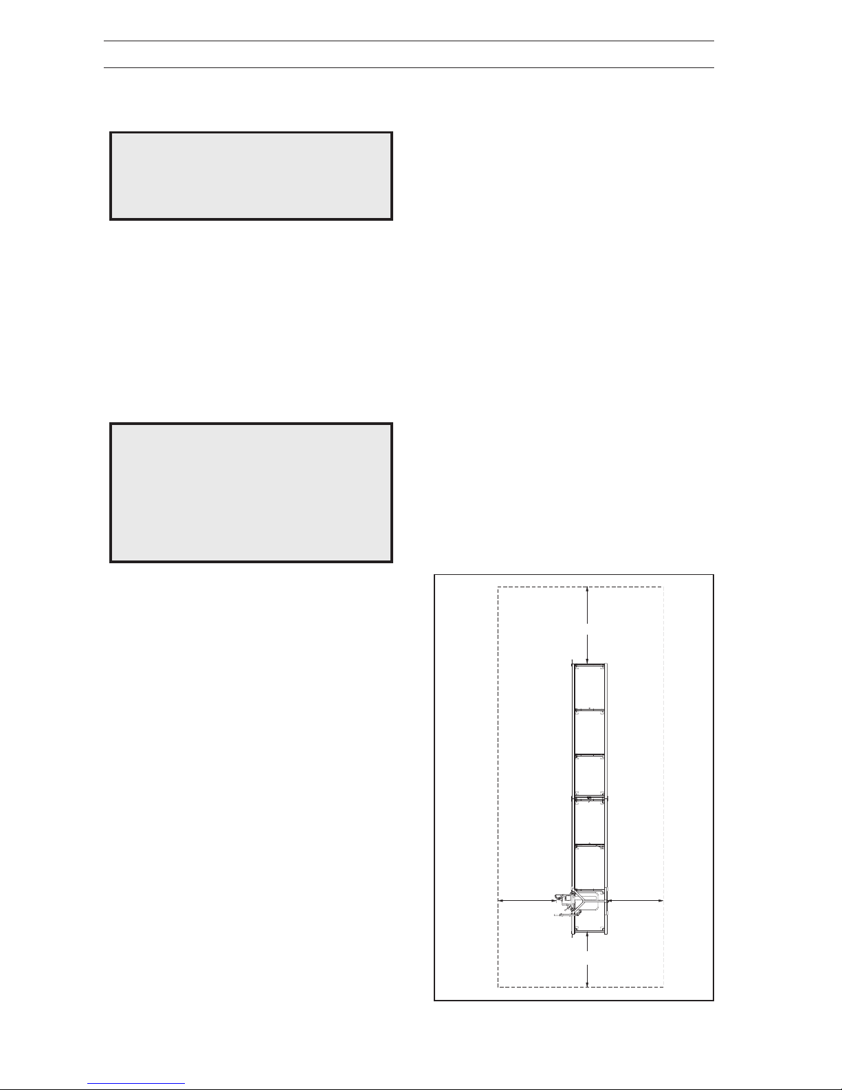
Risk Zone
The risk zone is evident from the picture to the right.
No unauthorised persons may be present in the risk
zone.
The risk zone should also be kept free of foreign
objects and the ground within the risk zone should be
flat so that the operator avoids stumbling.
Personnel
The following apply to personnel using the one-man
sawmill:
1. Shall have read and understood the content of this
operator’s manual.
2. Must not be under the influence of alcohol or
medication, nor suffering from tiredness.
3. Good lighting is required when using the sawmill
outside daylight hours.
4. Shall not be a minor.
5. Earthed circuit breaker recommended.
!
!
FIG. 1
Safety During Use
The safety regulations that apply while using the one-
man sawmill are documented in their respective areas
under the section Use on page 25-28.
The operator should observe the following safety
measures before and during use:
1. Check that all safety devices and guards are fitted
and undamaged.
2. Check that no fuel has been spilt on the outside of
the tank or on the ground.
3. Ensure that there are no people or animals within
the one-man sawmill’s risk zone.
4. The stopping and locking devices required to
fasten the log shall be used in the intended
manner. See pages 25-28.
5. Adjust the scale and check that the bandsaw
moves freely over the short and long log supports
by the red markings on the scale. See page 19,
FIG. 34.
3 m
5 m
3 m
3 m

English –7
One-man sawmill chain saw engine
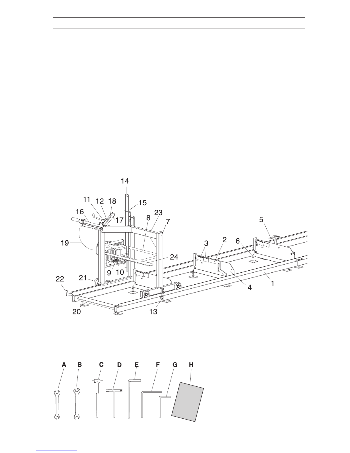
The one-man sawmill consists of two main parts:
•The carriage with engine and saw
•Rails
1. Rail sections (2)
2. Log lifter
3. Timber supports (short and long)
4. Log bolster
5. Log lock
6. Adjustment nut
7. Saw carriage
8. Protective loop
9. Vibration damping plate
10. Skid rail
11. Idler adjustment screw for saw height
12. Height setting lock
DESCRIPTION
13. Underlying support wheel
14. Scale pointer with scale
15. Indicator
16. Handlebars
17. Throttle
18. Throttle lock
19. Throttle cable
20. Support foot
21. Scraper
22. Rail stop
23. Machine plate
24. Bar and chain
Tools and operator’s manual
A. Open ended spanner 13-15 mm
B. Open ended spanner 17-19 mm
C. Socket spanner
D. Combination spanner 13-19
E. Combination spanner
F. Allen key 6 mm
G. Allen key 4 mm
H. This operator’s manual

8–English
DESCRIPTION
One-man Sawmill Electric Motor
The one-man sawmill consists of two main parts:
•The carriage with motor and saw
•Rails
1. Rail sections (2)
2. Log lifter
3. Timber supports (short and long)
4. Log bolster
5. Log lock
6. Adjustment nut
7. Saw carriage
8. Protective loop
10. Skid rail
11. Idler adjustment screw for saw height
12. Height setting lock
13. Underlying support wheel
14. Scale pointer with scale
15. Indicator
Tools and operator’s manual
A. Open ended spanner 13-15 mm
B. Open ended spanner 17-19 mm
C. Socket spanner
D. Combination spanner 13-19
E. Combination spanner
F. Allen key 6 mm
G. Allen key 4 mm
H. This operator’s manual
16. Handlebars
20. Support foot
21. Scraper
22. Rail stop
23. Machine plate
24. Bar and chain
25. Oil tank
26. Motor console
27. Connector with phase inverter
28. Electric motor
29. Start button electric motor
32. Stop button electric motor
37. Safety switch

English –9
DESCRIPTION
One-man sawmill with electric motor and feed
Tools and operator’s manual
A. Open ended spanner 13-15 mm
B. Open ended spanner 17-19 mm
C. Socket spanner
D. Combination spanner 13-19
E. Combination spanner
F. Allen key 6 mm
G. Allen key 4 mm
H. This operator’s manual
The one-man sawmill consists of three main parts:
- The carriage with motor and chain
- Feed unit
- Rails
1. Rail sections (2)
2. Log lifter
3. Timber supports (short and long)
4. Log bolster
5. Log lock
6. Adjustment nut
7. Saw carriage
8. Protective loop
10. Skid rail
11. Idler adjustment screw for saw height
12. Height setting lock
13. Underlying support wheel
14. Scale pointer with scale
15. Indicator
16. Handlebars
20. Support foot
21. Scraper
22. Rail stop
23. Machine plate
25. Oil tank
26. Motor console
27. Connector with phase inverter
28. Electric motor
29. Start button electric motor
30. Start button feed
31. Control for variable feed
32. Stop button electric motor
33. Feed wheel with cable
34. Cable adjustment
35. Feed motor
36. Electric cable with connector
37. Safety switch

10 –English
DESCRIPTION
Saw carriage (FIG. 2)
The saw carriage comes in the same version for all
one-man sawmill models and comprises the following
parts:
•Steel structure with runner wheels against the rails
and guides for the saw’s up and down movement.
•One screw for the saw’s vertical adjustment. The
screw is operated by a crank and is equipped with
an index plate.
•Handle with operating mechanism.
•Vibration damping plate (One-man sawmill with
chain saw engine)
•Motor console (One-man sawmill with electric motor)
•Bar and chain
•Chain oil tank for the chain (One-man sawmill with
electric motor)
A suitable chain saw is also installed on the saw
carriage.
Height Setting (FIG. 4)
The saw unit is secured vertically by a screw. A crank
(11) is fitted on the top section of the screw, and is
used to set the exact dimension of the timber
thickness. One turn of the crank moves the bandsaw
blade 5 mm. The height of the bar above the rails’
cross members is read on the scale (14). There are
two red markings on the scale that indicate the lowest
saw height with the timber support raised, one red line
for the long timber support and one red line for the
short one. CAUTION! Sawing under the respective
markings will damage the chain and there will be a risk
of sparking.
Frame (FIG. 3) and (FIG. 4)
The carriage frame consists of welded square tubing
with requisite corner reinforcement for stability during
cutting. The console is installed in the saw carriage for
the saw unit’s up and down movement. On the under-
side of the frame are four runners, fitted with bearings,
with slots for securing and smooth running along the
rails. The carriage is equipped with two adjustable
bearings, which run against the underside of the rails,
to prevent it from lifting.
FIG. 2
FIG. 3
FIG. 4
Handlebars (FIG. 4)
The saw carriage is operated and moved forwards
using handlebars (16), which are located on the left-
hand side of the saw carriage.The handlebars are
equipped with a throttle for start lock (17, 18). On the
one-man sawmill with feed, the handlebars are used
for feeding when you want to approach the end of the
log to calculate the saw yield.
16
18
17
11
14
Questo manuale è adatto per i seguenti modelli
1
Indice
Altri manuali Jonsered Sega