Jordan Valve I&M Mark 508UBS Istruzioni per l'installazione e il funzionamento

3170 Wasson Road • Cincinnati, OH 45209 USA
Phone 513-533-5600 • Fax 513-871-0105
[email protected] • www.jordanvalve.com
I & M Mark 508UBS
Installation & Maintenance Instructions for
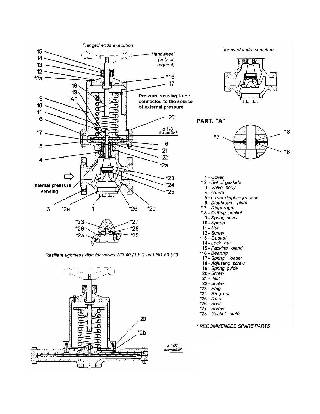
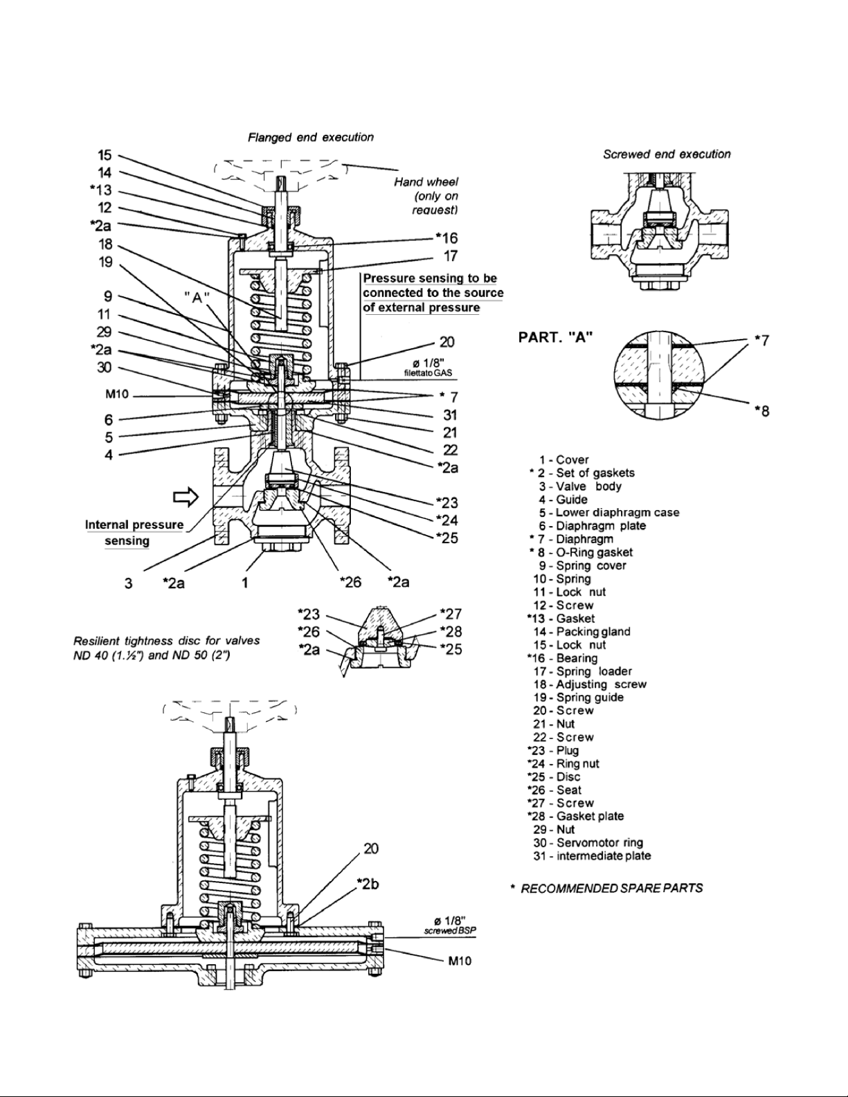
Mark 508UBS Back Pressure Regulators
Warning: Thorough maintenance operations and overhauls are important for the safe and reliable operation of all
valves. The service procedures recommended by Jordan and described in this manual are for carrying out main-
tainance operations. Please note that this service manual contains various warning and caution notices which
should be read carefully in order to minimize the risk of injury to people or the possibility of using incorrect work
methods which may damage the valves or make them unsafe. It is important to realise, however, that these warn-
ings cannot be exhaustive. Jordan is unable to know, assess and inform customers or users of all the conceivable
methods of performing maintainance operations and all the risks deriving from the use of such methods. Therefore,
whoever uses a service method or piece of equipment which is not recommended by Jordan must make sure that
neither his own or other people’s safety, nor valve safety and performance are jeopardized by the chosen method.
Testing, installing or removing the valves or accessories may cause you to come into contact with fluids at very high
pressures or temperatures and/or corrosive or erosive. Therefore, take all safety precautions while testing, install-
ing or removing the product; these include, wearing ear plugs, goggles and safety clothing, such as gloves, both in
or near the work area. Users of Jordan products are responsible for training the staff that will use the product. It is
most important for these people to acquire a thorough knowledge of the instructions of the product, especially the
ones contained in this manual.
Please read these instructions carefully!
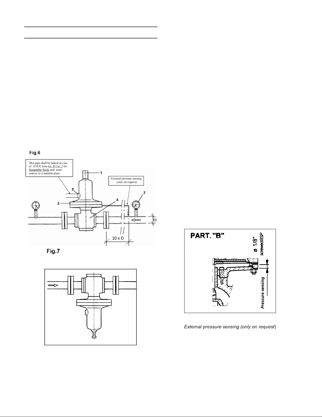
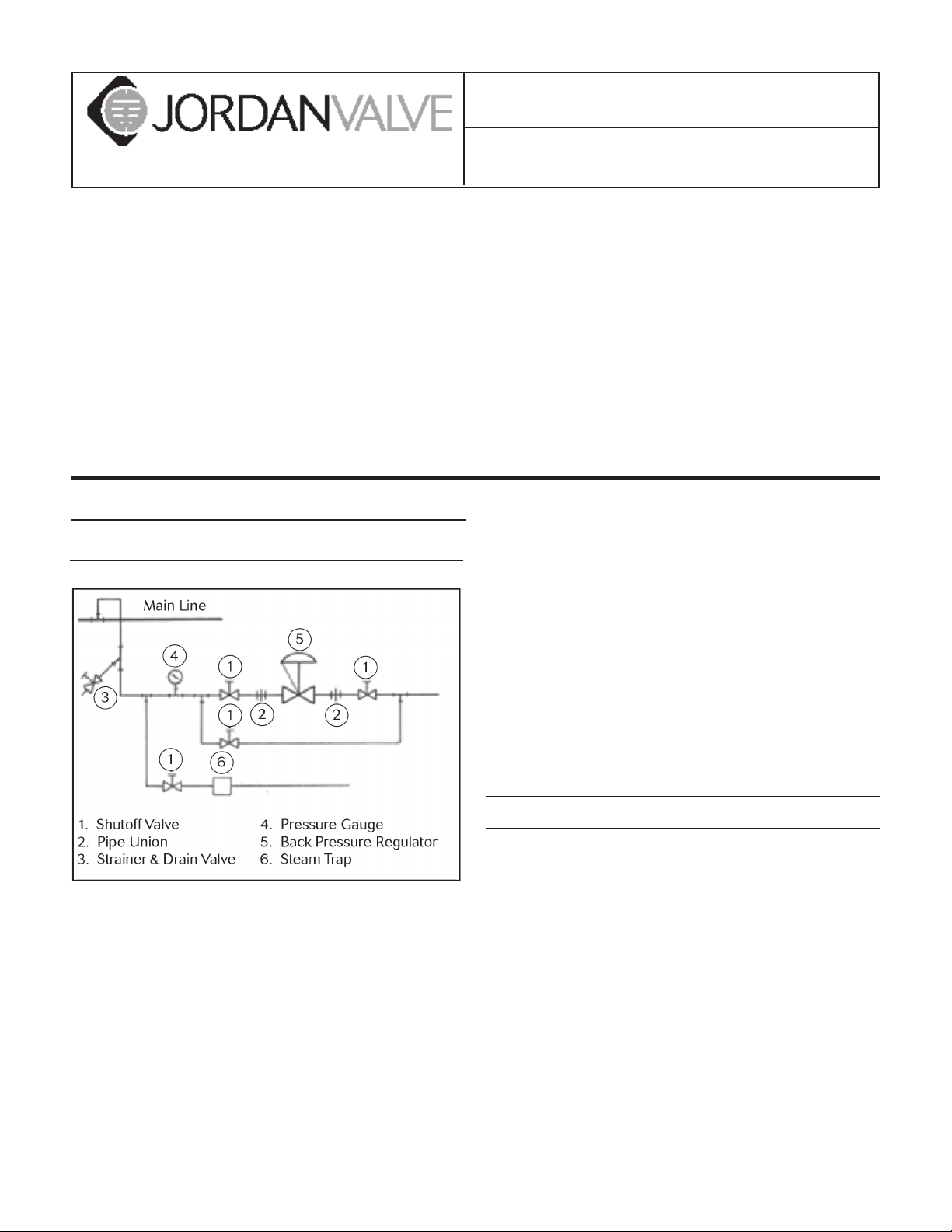
Ideal Installation
Safety Precautions
Always observe the current plant safety regulations to-
gether with the following indication:
• Wear safety clothing. Hot water can scald you and
overheated steam is invisible.
• When removing a valve, wear safety clothing to pre-
vent being sprayed by any process fluid that may
have accumulated inside. Remember that this fluid
may generate a potentially explosive mixture. Make
sure the valve is isolated from any pressure source
in the system before staring to remove it.
• Inspect/ service the valves at least once a year.
The outer surfaces of the valves reach the same tem-
perature as that of the fluid flowing inside them. For
this reason, when installing a valve in a potentially
explosive atmosphere, make sure that the flashover
temperature of the mixture surrounding the valve is
safely above that of the fluid flowing inside the valve
and do not allow flammable powders to deposit on
the outer surface of the valve.
• The system must be at zero static potential at the
connection between the valve and the piping in or-
der to prevent the accumulation of static electricity
on the outer surfaces of the system that can act as
an efficient flashover trigger in a potentially explosive
atmosphere.
Transport, Storage & Handling
Transport
Depending on their size, valves can be transported
loose, packed in cardboard boxes or in wooden crates.
All of the valve ends are fitted with covers to prevent
dirt from entering. Packs can be places on pallets if
required. Follow all and any indications written on the
packaging.
Storage
Valves must be kept in a dry place to protect them from
atmospheric conditions. They may only be removed
from their crates or packing immediately prior to instal-
lation. The end protections and covers must be kept on
until the last moment. Valves, whether packed or not,
must not be subject to violent knocks. Valves, whether

Note: The actuators with diameter 220 and 360 in
carbon steel or stainless steel are provided with a de-
composed spring cover.
packed or not, must be kept upright, that is, never lying
on one side, in order to prevent distortion and damage
to internal parts.
Handling
When unpacking the valves and removing the end pro-
tectors immediately prior to installation, take great care
to make sure that foreign bodies do not enter the valve
inlet and outlet holes while it is being connected.
-2-

-3-
Installation
The UBS and UBS/V valves must be installed with the
spring housing (2) facing upwards and the diaphragm
horizontal, as shown in Fig. 6. In overflow valves regu-
lating very low pressures (normally lower than 100 mm
water column; the rating plate is always installed upside
down and is therefore indicative), they must be installed
with the actuator facing downwards and horizontal, as
shown in Fig. 7; the weight of the mobile equipment
is greater than the force of the pressure regulated on
the diaphragm and must therefore be supported by the
spring.
Before installation the valve on the piping, make sure the
insides of the pipes are clean, especially the upstream
section; blow down the piping if possible to eliminate
any remaining dirt: small drops of solder mat seriously
damage the valve.
1.) Adjustment screw
2.) Actuator
3.) Pressure gauge
4.) Valve body
5.) Drain hole
WARNING ON ATEX: the spring cover is not airtight
(
ATEX form Gr. II Cat. 2 for non-flammable fluids
- Fig.
3 in case of harmless fluids (e.g., inert gases like ni-
trogen, carbon dioxide, noble gases). It’s equipped
with a hole (see fig. 6/7), whose chief function is that
to drain the pressure whether the diaphragm cracked.
Meanwhile in case of flammable fluids the spring
cover is airtight (
ATEX form Gr. II Cat. 2 for flammable
fluids
- Fig. 4), made from carbon steel and stainless
steel, the hole (5) in Fig. 6 and 7 is always threaded
1/4” NPT and must be connected to pipe convey-
ing the discharge to a suitable place (at atmospheric
pressure).
Please bear in mind that the regulated pressure sensing
is located inside the valve, for which reason the pressure
drops in the piping connecting the valve to the ambient
under control must be added to the calibration pressure
value. This must be considereting when calculationg the
size of the above piping.
When it is essential to avoid pressure variations at the
point of use, the valves are fitted with an external pres-
sure sensing, as shown in Fig. 6. In that case connect
the actuator to the sensing line upline at a distance of at
least 10 times pipe diameter ‘D’.
The sensing line must always be connected to the side
of the main pipe or on top of it, never underneath, other-
wise solids substances may obstruct the pressure sens-
ing.
To remove the valve, attach the joints in three pieces in
the appropriate positions on the sensing line. The 1/8”
female threaded connector is shown in Part “B”.
Generally speaking, the fluid crossing the overflow valves
has been checked to make sure it is clean; if there are
any doubts about this, fit a filter upline from the overflow
valves.
If in the plant there is the possibility that the pressure in
contact with the diaphragm exceeds the maximum dia-
phragm rating, it is necessary to install the safety relief
device show in Fig. A. The device is installed on the low-

er diaphragm case, through a 1/8” Gas female threaded
hole and a threaded nipple 1/8” Gas male 3/8” Gas
female (on the opposite side respect the pressure sens-
ing in case of external pressure sensing construction). It
consists (see Fig. A) in a plug, pressed by a spring prop-
erly calibrated depending on the maximum diaphragm
rating, that can move inside a cylindrical body, due to the
fluid action, gradually discovering a 1/4” NPT threaded
female discharge hole. The discharge flow, discharged
versus ground, can be realeased in atmosphere or prop-
erly collected, depending on working medium. If this is
an ATEX version of the valve the discharge flow must be
collected in inert atmosphere, through an appropriate
tube with 1/4 “ NPT male threaded connection, to avoid
the potential generation of explosive mixtures.
Fig. A
Start-Up and Calibration
Regulation equipment is normally supplied calibrated to
the value indicated in the order;
the set pressure must
be checked in real operating conditions
.
If the valve does not open at the required set pressure,
loosed the lock nut (14) and turn the adjustment screw
(13) clockwise to increase overflow pressure or anti-
clockwise to reduce it; in case of construction with seal
cap (Fig. 4), first remove the cap (28).
After checking set pressure, tighten the lock nut (14); re-
install the cap (28) in case of construction with seal cap
(Fig. 4).
ATTENTION! During Valve start-up or operation, do
not touch any part of the valve as this can conduct
heat if the fluid used it at a high temperature.
Maintenance
If the regulated fluid is clean and the plant is fitted with
a filter, maintenance operations will be infrequent occur-
rences.
The user much check the seats
at least once a year
depending on the need for the valve to close airtight.
When performing this inspection, the interval compo-
nents can be removed without removing the body from
the line, but it is easier to work if the entire valve is re-
moved from the piping. Before starting the above opera-
tion, make sure the recommended spare parts are avail-
able (Figs. 1-2-3-4-5, parts list).
Removing the Components
(see Figs, 1-2-3-4-5)
Removing the Actuator
Removing the spring by unscrewing the adjustment
screw (13) after loosening the lock out (14), leaving it in
position or noting down its position on the adjustment
screw in order to restore calibration after reassembly.
If the spring housing is airtight (Fig. 4), first remove the
cap (28) with gasket (2c). Remove the spring cover
(11) by loosening the nuts (19); do not disassemble the
spring cover of teh 220 and 360 actuators.
Remove the spring (12). Unscrew the nut (16). Remove
the diaphragm (8), after having removed spring guide
(18) and diaphragm plate (7).
Removing the Body
Unscrew and remove the cover (1) with gasket (2a). Un-
screw the seat (25) with a screwdriver (see Figs. 1, 2 and
5).
Pull the plug (22) off its guide (4) and remove it from the
body (3).
Parts Inspection
All the components are now ready to be inspected. Re-
place any worn ones. Clean all the parts. In particular,
check the state of the disk of the plug (24), both elastic
and metal, and the seat of the orifice (25). If the seat is
-4-

worn, work it by rubbing with a metal disk and abrasive
paste. If this is not enough, rework it on the lathe. If
no expert operators are available, send the whole valve
back to our factory for revision. Another important com-
ponent to control is the diaphragm (8); replace it if the
surface is in poor condition. The same applies to the
Teflon protection. Replace all the gaskets (2a-b-c-d),
at
least once a year
, after cleaning the surfaces they lie on.
Reassembly
Carry out the removal operations in reverse order.
Fit the stem of the plug (22) into the body (3) and push
it onto its guide (4). Tighten the seat (25), making
sure that the relevant gasket (2a) is new and correctly
positioned. Replace the small rentention ring (10) after
thoroughly cleaning its seat.
Install the diaphragm (8), taking care to install the pro-
tection (9), where applicable, underneath, towards the
valve body, lying on the little plate (20). Reinstall the
disk (7) and the spring guide (17), and fully tighten the
nut (16).
Match the holes of the diaphragm with the ones in the
lower diaphragm case (5) and reinstall the spring (12),
spring loader (15) and cover (11). Screw back the cover
(1). Return the screw (13) to the position marked by the
nut (14) or the position you noted down (see 8.4.2.1).
Exact calibration must then be checked whe the valve
starts working again.
Replacing the Diaphragm Only
If the diaphragm deteriorates or breaks during opera-
tion or requires replacement without having to perform
any other maintenance operations and if the valve is
east to access, perform the operations listed in para-
graph “Removing the Actuator”, leaving the valve on the
piping, preventing the operating medium inflow to the
valve itself and discharging the pressure on the main
line. At the end of operations proceed to reassembly
with inverse operations from those described in para-
graph “Removing the Actuator”.
Check calibration once more whe the valve starts work-
ing again and adjust if necessary.
After each maintenance operation, replenish your stock
of spare parts by reordering used items.
ATTENTION! When welding piping, do not attach the
earth connector to the valve as this may damage
important sliding parts.
-5-

Note: The actuators with diameter 220 and
360 in carbon steel or stainless steel are pro-
vided with a decomposed spring cover.
-6-

Installation
Before installing the valve, remove the plastic covers
protecting the flanges or connectors.
Make sure the data indicated on the rating plate cor-
responds to operating conditions.
ATTENTION! Check that the maximum positive pressure
that can occur in the equipment being protected does
not exceed the following values:
Diameter of Actuator
in mm
Maximum positive
pressure in bar
* 360 1.5
* 220 5
* This data can be derived from the valve code shown
on the rating plate.
Before installing the valve in the piping, make sure the
insides of the pipes are clean, especially the upstream
section; blow down the piping if possible to eliminate
any remaining dirt: small drops of solder may seriously
damage the valve.
ATTENTION! The valve must always be installed with
the actuator facing down. The section of the inlet
tubing at atmospheric pressure must also face down-
wards in order to prevent impurities or water from
depositing at the valve inlet in the event of oudoor
installations.
Start-Up and Calibration
Valves are normally supplied calibrated to the value in-
dicated in the order. This calibration must be checked
in real operating conditions.
If the valve does not open at the required calibration
value, remove the cap (28), loosen the lock nut (14) and
turn the adjustment screw (13) clockwise to increase
overflow pressure or anti-clockwise to reduce it. After
checking opening pressure, start the plant at full power
and adjust calibration as required by turning the adjust-
ment screw (13); then tighten the lock nut (14).
Maintenance
ATTENTION! Before removing the valve, make sure the
recommended spare parts are available (fig. 8). After
each operation, replenish your stock of spare parts by
reordering used items.
ATTENTION! Only use original spare parts.
If the regulated fluid is clean and the plant is fitted with a
filter, as recommended, maintenance operations will be
infrequent occurrences.
The user must check the seats at least once a year de-
pending on the need for the valve to close airtight. When
performing this inspection, the internal components can
be removed without removing the body from the line, but
it is easier to work if the entire valve is removed from the
piping.
REMOVING THE COMPONENTS
Removing the Actuator
Remove the cap (28) and release the spring by unscrew-
ing the adjustment screw (13) after loosening the lock
nut (14), leaving it in position or noting down its position
on the adjustment screw in order to restore set pressure
after assembly.
Remove the spring cover (11) by unscrewing the nuts
(19); do not disassemble the spring cover. Remove the
spring (12). Unscrew the nut (16). Remove the dia-
phragm (8), after having removed spring guide (18) and
upper diaphragm plate (7).
Removing the Body
Unscrew and remove the cover (1) with gasket (2a).
Unscrew the seat (25) with a screwdriver (Fig. 8).
Pull the plug (22) off its guide (4) and remove it from the
body (3).
Parts Inspection
All the components are now ready to be inspected.
Replace any worn ones. Clean all the parts. In particular,
check the state of the disk of the plug (24) and the seat of
the orifice (25).
Reassembly
Carry out the removal operations in reverse order.
Fit the stem of the plug (22) into the body (3) and push it
into its guide (4).
Tighten the seat (25), making sure that the relevant
washer is in good condition and correctly positioned.
-7-

Replace the small retention ring (10) after thoroughly
cleaning its seat.
Install the diaphragm (8), taking care to install the pro-
tection (9), where applicable, towards the area in con-
tact with the tank fluid, fitted between the diaphragm (8)
and the upper diaphragm plate (7). Reinstall the upper
diaphragm plate (7) and spring guide (17), and then fully
tighten the nut (16). Match the holes of the diaphragm
with the ones in the lower diaphragm case and reinstall
the spring (12), spring loader (15) and cover (11). Screw
back the cover (1). Return the screw (13) to the position
marked by the nut (14) or the position you noted down
(see 9.2.4). Exact set pressure must then be checked
when the starts working again.
Replacing the diaphragm only
If the diaphragm deteriorates or breaks during opera-
tion or requires replacement without having to perform
any other maintainance operations and if the valve is
easy to access, perform the operations listed in para-
graph “Removing the Actuator”, leaving the valve on the
piping, and closing the shut off valves (4) Fig. 9 on the
main line and sensing line. At the end of operations
proceed to reassembly with inverse operations from
those described in paragraph “Removing the Actuator”.
Check calibration once more when the valve starts
working again and adjust if necessary.
Operating Faults
FAULT REASON ACTION
Leaking while the
valve is closed for
valves also working
with positive
pressure
Valve not airtight Remove the valve and
replace the gasket.
Difficulty in adjust-
ing the vacuum in
the tank for valves
only working in a
vacuum
Valve out of
calibration
Check calibration as
per point 9.3
Valve not airtight Remove the valve and
replace the gasket.
Diaphragm
broken
Remove actuator as-
sembly and replace
the diaphragm, O-ring
and spring cover,
where applicable.
Gaskets 2A, 2B,
2C, and 2D worn Replace the gaskets
-8-

UBS/D1
Note: Actuators with diameter 220 and 360
in carbon steel or stainless steel are provided
with a two piece spring cover.
-9-

UBS/ D2
-10-
Indice
Altri manuali Jordan Valve Controllori

Jordan Valve
Jordan Valve STERIFLOW Mark 95LL Series Istruzioni per l'installazione e il funzionamento

Jordan Valve
Jordan Valve I & M Mark 4150 Series Istruzioni per l'installazione e il funzionamento

Jordan Valve
Jordan Valve LowFlow Mark 709 7M Istruzioni per l'installazione e il funzionamento

Jordan Valve
Jordan Valve Mark 60 Series Istruzioni per l'installazione e il funzionamento

Jordan Valve
Jordan Valve STERIFLOW CSDT Series Istruzioni per l'installazione e il funzionamento

Jordan Valve
Jordan Valve I 60 Istruzioni per l'installazione e il funzionamento


