JRC JLR-7700MKII - Manuale utente

1
JLR-7700 MK2GPS Navigator
Foreword
Thank you for choosing the JLR-7700 MK2GPS navigator.
This equipment is a high-performance navigation equipment consisting of a DGPS receiver and navigator,
can retrieve the position data using the DGPS receiver to display various navigation information on the
display.
●Thoroughly read this instruction manual before commencing the equipment operation.
●We would recommend you to keep this manual nearby the equipment to ensure readily access to it.
It should give you information how to cope with a given situation that may arise during the equipment
operation.
2
JLR-7700 MK2GPS Navigator
Before Commencing the Equipment Operation
Graphical Symbols
Several graphical symbols are used in this manual to ensure safety and proper
operation of the equipment and to avoid possible human injury or property
damage. The symbols and their meanings are shown below. We would
recommend you to carefully read the manual to obtain a thorough
understanding on these symbols.
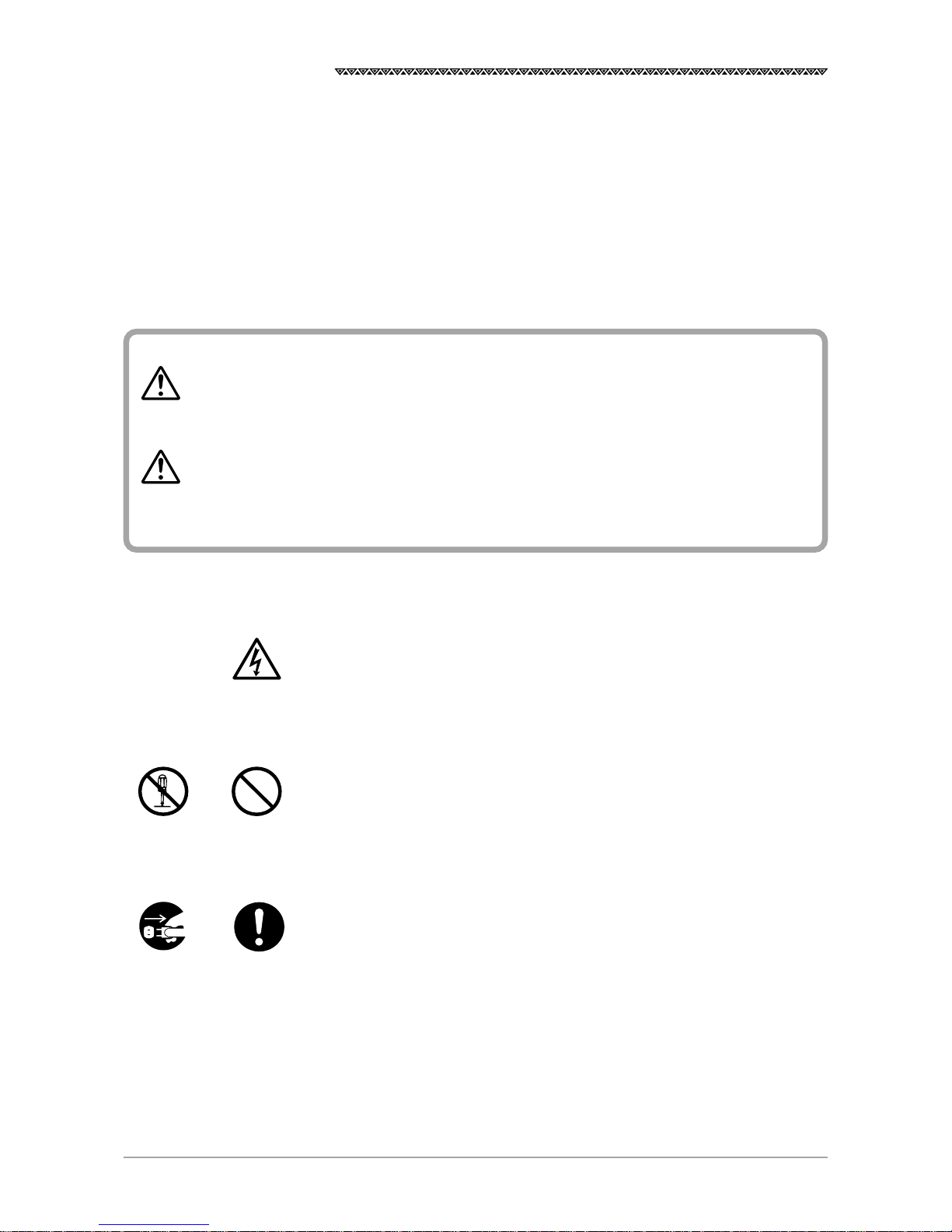
Examples of the Symbols
The symbols shown in the △mark represent those that require attention
(including the potential dangers and warnings).
A tangible instruction is shown in the symbol. For example, the symbol shown
to the left indicates that one is likely to get an electric shock.
The circle symbols with a slash from the upper left to the right bottom
represent the specific actions prohibited to avoid potential hazards.
A tangible instruction is shown in the symbol. For example, the symbol shown
to the left indicates that the disassembly is prohibited.
The black circle symbols represent the obligatory actions or instructions to
avoid potential hazards.
A tangible instruction is shown in the symbol. For example, the symbol shown
to the left indicates that the power supply plug needs to be disconnected.
Instructions shown with this symbol represent those
that can cause death or severe injury, if not observed.
Instructions shown with this symbol represent those
that can cause injury or property damage, if not
observed.
Don’t
disassemble
Don’t
Disconnect
the power
supply plug
Instruction
Electric shock
WARNING
CAUTION
3
JLR-7700 MK2GPS Navigator
POWER
OFF!
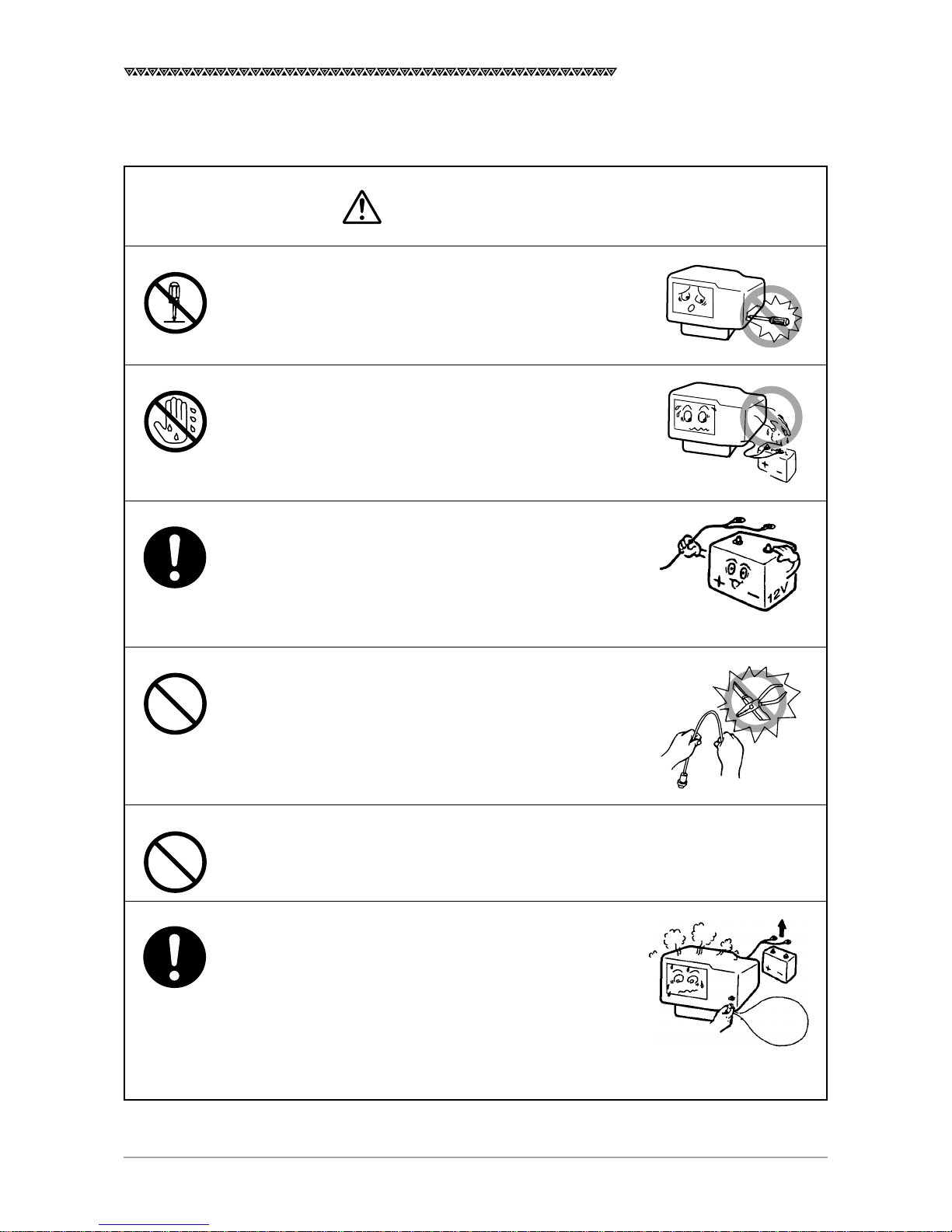
Precautions Upon Equipment Operation
Do not disassemble or modify the equipment. Failure
to observe the instruction can cause a fire, electric
shock, or equipment failure.
Do not connect or disconnect the power supply cable
with a wet hand. Otherwise, you may suffer from an
electric shock.
Operate the equipment only at the power supply
voltage of 12 or 24 VDC. Failure to observe this
instruction can cause a fire, electric shock, or
equipment failure.
Do not scratch, damage, or modify the power supply
and antenna cable. It may be damaged to cause a fire
or electric shock if it is loaded with a heavy item, heated,
pulled, or excessively bent.
Do not operate the equipment while steering the
vessel. It can cause accidents.
Immediately turn the power off and disconnect the
power supply cable if the equipment is generating any
smoke or odor, or found overheated. Then, promptly
inform our local service agent of the symptom to have
it corrected. Prolonged equipment operation under
such a condition can cause a fire or electric shock.
WARNING
4
JLR-7700 MK2GPS Navigator
Thinner
Benzine
No
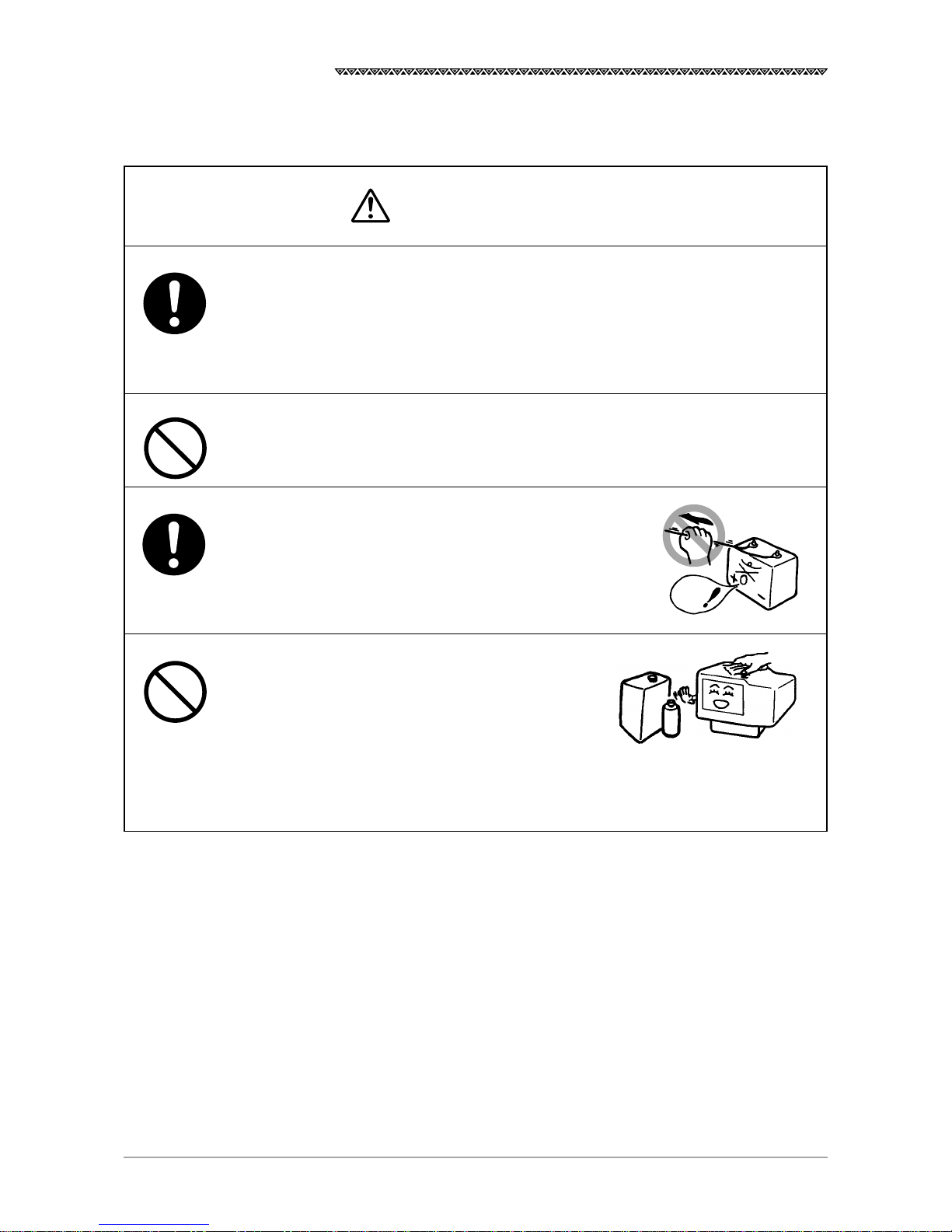
This equipment is not designed to automatically make
judgments on the position data. The navigation
information including the position data needs to be
judged by the user himself.
Do not allow the equipment to fall or immerse in water.
The equipment can be damaged.
When removing the power and antenna cord, be sure
to remove the cord terminal correctly. If the cord is
pulled, the cord may be damaged resulting in a fire or
an electrical shock.
When cleaning the surface, do not use any or-
ganic solvent such as thinner or benzine.
Otherwise, the painting on the surface may be
damaged.
For cleaning the surface, remove the dust and
refuse and wipe with clean dry cloth.
Our contacts
Refer to the List of Offices attached at the end of this manual.
CAUTION
5
JLR-7700 MK2GPS Navigator
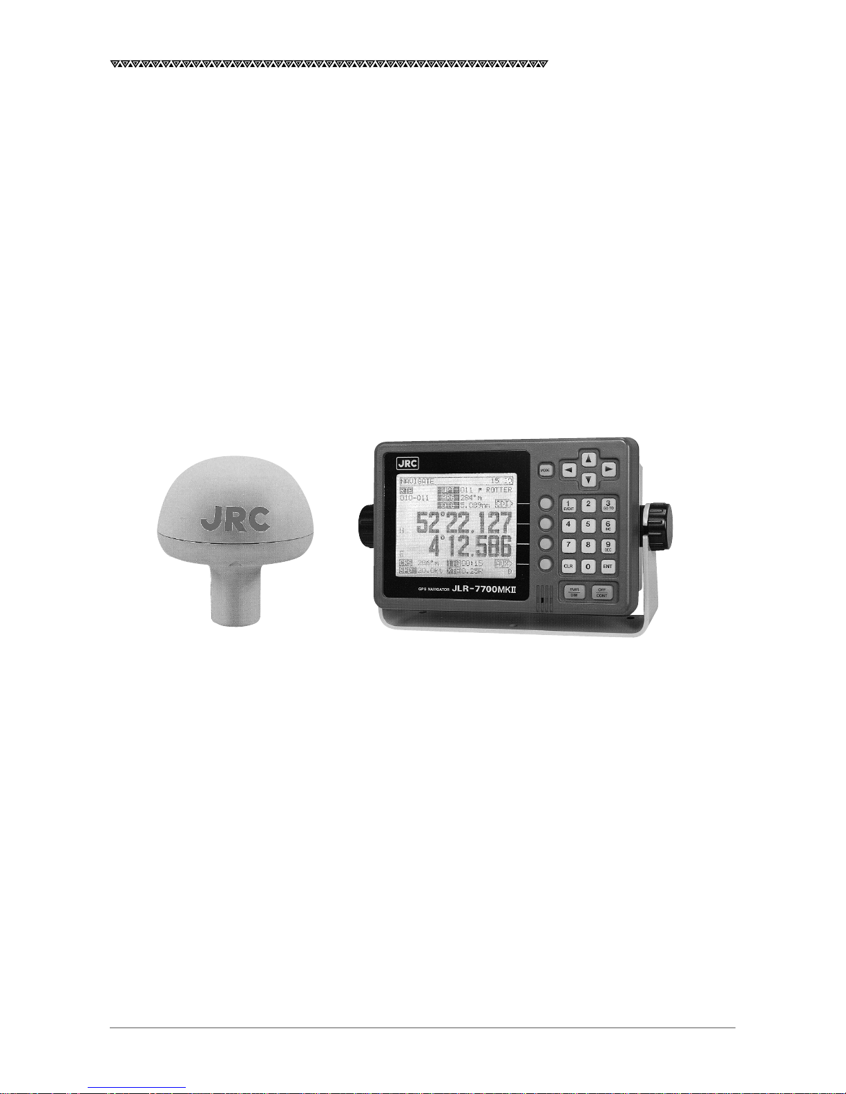
Appearance of the Equipment
DGPS Receiver Navigator

6
JLR-7700 MK2GPS Navigator
Table of Contents
Foreword ............................................................................................................................. 1
Before Commencing the Equipment Operation................................................................... 2
Precautions Upon Equipment Operation............................................................................. 3
Appearance of the Equipment............................................................................................. 5
Key Terms............................................................................................................................ 9
1. Equipment Overview ................................................................................................... 11
1.1 Functions .......................................................................................................................................11
1.2 Features .........................................................................................................................................12
1.3 Configuration .................................................................................................................................13
1.4 Construction ...................................................................................................................................14
1.5 Generall System Diagram ..............................................................................................................17
2. Unit Descriptions and Functions ................................................................................. 18
2.1 Operation Panel of the Navigator...................................................................................................18
2.2 Rear Panel of the Navigator ...........................................................................................................20
2.3 DGPS Receiver .............................................................................................................................21
3. Installation ................................................................................................................... 22
3.1 Installation of the DGPS Receiver .................................................................................................22
3.1.1 Selecting the Position for Installation .......................................................................................22
3.1.2 Installation Procedure of the DGPS Receiver..........................................................................23
3.1.3 Installation of the DGPS Receiver on the Mast .......................................................................24
3.2 Installation of the Navigator ...........................................................................................................25
3.2.1 Selection of the Installation Location .......................................................................................25
3.2.2 Installation of the Navigator .....................................................................................................26
3.3 Installation of the Junction Box ......................................................................................................28
3.3.1 How to Mount the Junction Box on the Mast ...........................................................................28
3.3.2 Pole Mounting Kit .....................................................................................................................29
3.3.3 How to Mount the Junction Box on a Flat Surface ...................................................................29
3.4 Connection of the Navigator ..........................................................................................................30
3.4.1 Connection of the Power Supply Cable ...................................................................................30
3.4.2 Connection of the Grounding Line ...........................................................................................30
3.4.3 Connection of the DGPS Receiver ..........................................................................................31
3.4.4 Data Output .............................................................................................................................32
3.4.5 Relay Output ............................................................................................................................33
3.4.6 Connection of the Junction Box ...............................................................................................34
3.4.7 Connection of the Waterproof Connectors (2, 6, or 7-pin Connector) .....................................35
3.4.8 Connection Cable (Optional Unit) ............................................................................................35
3.5 Measures for the Electromagnetic Interference .............................................................................36
3.5.1 Checks before the Connection ................................................................................................36
3.5.2 Checks before the Navigation ..................................................................................................36
3.6 How to Connect the NQA-602DC Buffer Unit (Optional Unit) ........................................................ 37
3.7 Connection of the NBA-3581A AC Power Supply Unit (Optional Unit) ..........................................37
3.8 Connection of the NKG-22 Printer (Optional Unit) .........................................................................38

7
JLR-7700 MK2GPS Navigator
4. Operation Method ....................................................................................................... 39
4.1 Basic Operations ...........................................................................................................................39
4.1.1 Turning the Power ON and OFF ..............................................................................................39
4.1.2 Selection of the Language .......................................................................................................39
4.1.3 Contrast Adjustment ................................................................................................................39
4.1.4 Backlight Adjustment ...............................................................................................................40
4.1.5 Return to the SELECT MODE Screen.....................................................................................40
4.2 Screens ..........................................................................................................................................40
4.2.1 Display and Operation List for the NWZ-4570B Navigator ......................................................41
4.3 How to use the Navigation Information Screens ............................................................................ 42
4.3.1 NAVIGATE Screen ...................................................................................................................42
4.3.1.1 Setting a Destination .........................................................................................................43
4.3.1.2 To Change the Leg (Manual Leg Change) ........................................................................ 45
4.3.1.3 To Skip (Omit) a Destination .............................................................................................. 45
4.3.1.4 Canceling the Route ..........................................................................................................46
4.3.1.5 Storing the Current Position (Event) ..................................................................................46
4.3.2 COURSE DEVIATION IND. Screen .........................................................................................47
4.3.2.1 Switching the CDI Meter Scale .......................................................................................... 47
4.3.2.2 Switching the Display on the Two Bottom Lines ................................................................47
4.3.3 NAVIGATE AUX Screen ...........................................................................................................49
4.3.3.1 Magnetic Compass Correction .......................................................................................... 49
4.3.3.2 Setting the Display Unit .....................................................................................................50
4.3.3.3 Selection of the Data Output Format .................................................................................50
4.4 PLOT Screen (Tracked Line Screen) .............................................................................................51
4.4.1 PLOT Screen ...........................................................................................................................51
4.4.1.1 Setting the Horizontal Scale Range...................................................................................51
4.4.1.2 Setting the Plot Interval .....................................................................................................51
4.4.1.3 Erasing the Tracked Line ...................................................................................................52
4.4.1.4 Setting a Destination .........................................................................................................52
4.4.1.5 To Store the Current Position ............................................................................................. 52
4.4.1.6 Turning ON and OFF the Display for the Two Bottom Lines .............................................. 52
4.4.1.7 To Display the Current Position at the Center of the Screen .............................................52
4.4.2 PLOT AUX Screen ...................................................................................................................53
4.4.2.1 Setting the Geodetic System .............................................................................................53
4.4.2.2 Entering the Correction Values for Latitude and Longitude ............................................... 53
4.4.2.3 Setting the DGPS BEACON ..............................................................................................54
4.5 Registration the Waypoint ..............................................................................................................55
4.5.1 WAYPOINT Screen ..................................................................................................................55
4.5.2 WAYPOINT LIST Screen .........................................................................................................57
4.5.2.1 Copying the Waypoint Data ............................................................................................... 57
4.5.2.2 Erasing the Waypoint Data ................................................................................................57
4.5.3 ROUTE SEQUENCE Screen ................................................................................................... 58
4.5.3.1 Setting the Route Plan ....................................................................................................... 58
4.5.3.2 Canceling the Route Plan ..................................................................................................58
4.5.3.3 Setting the Arrival Alarm Range ........................................................................................59
4.5.3.4 Switching between the Automatic and Manual Leg Change .............................................59
4.5.3.5 Switching between Great-circle and Rhumb-line ............................................................... 60

8
JLR-7700 MK2GPS Navigator
4.5.4 Setting the Navigation Alarms .................................................................................................61
4.5.4.1 Setting the Arrival Alarm Range ........................................................................................61
4.5.4.2 Setting the Off-Course Alarm Range .................................................................................61
4.5.4.3 Setting the Anchor Alarm Range .......................................................................................62
4.5.4.4 Setting the Boundary Alarm Range ...................................................................................63
4.6 SAT STATUS Screen......................................................................................................................64
4.6.1 INITIAL SETTING Screen........................................................................................................ 64
4.6.1.1 Setting the Initial Data .......................................................................................................64
4.6.1.2 Setting the Loran Station ...................................................................................................65
4.6.1.3 Search the Sky .................................................................................................................. 65
4.6.1.4 Master Reset .....................................................................................................................65
4.6.2 GPS AUX Screen ....................................................................................................................66
4.6.2.1 Setting the Averaging for Position Display ......................................................................... 66
4.6.2.2 Setting the HDOP Level .....................................................................................................67
4.6.2.3 Setting the Antenna Mode .................................................................................................68
4.6.3 Weather Information ................................................................................................................68
4.7 Special Functions ..........................................................................................................................69
4.7.1 Loran Time Difference Display .................................................................................................69
4.7.1.1 Setting the Loran A Station................................................................................................69
4.7.1.2 Setting the Loran C Station ............................................................................................... 70
5. Maintenance and Inspection ....................................................................................... 72
6. Measures for the Operating Environment ................................................................... 73
7. After-the-sale Services ................................................................................................ 74
8. Disposal ......................................................................................................................75
8.1 Disposal of the Equipment .............................................................................................................75
8.2 Disposal of the used Battery ..........................................................................................................75
9. Specifications .............................................................................................................. 77
Attachments
Attachment 1 Optional Units ...........................................................................................................80
Attachment 2-A List of Messages ...................................................................................................... 84
Attachment 2-B List of Geodetic Systems ..........................................................................................86
Attachment 2-C NMEA0183 Output Sentence Data Format ..............................................................88
Attachment 2-D Table of Waypoints ...................................................................................................94
List of Offices .................................................................................................................... 96

9
JLR-7700 MK2GPS Navigator
Key Terms
TermDescription
GPS satellites The term is an acronym that represents the Global Positioning System,
which is managed by the US Department of Defense to support its
navigation aid system.
DGPS The term is an acronym that represents the Differential Global
Positioning System, which is a system to improve the position fixing
accuracy by receiving the correction data with a beacon receiver for a
given GPS satellite, which is transmitted by the beacon station with a
known position.
Position fixing The term means to obtain the current position of your vessel with the
GPS or DGPS receiver.
2D (Two-dimensional position fixing) The term 2D means the position fixing with data obtained from the satel-
lites and antenna height information.
3D (Three-dimensional position fixing)
The term 3D means the position fixing with four or more satellites infor-
mation only.
HDOP The term is an acronym that represents the Horizontal Dilution of
Precision, which reflects the position fixing accuracy. The accuracy
increases as the value decreases.
The value increases when the satellites are gathered close to each other,
and it reduces when the satellites are spattered, which in turn means
increased accuracy.
Loran time difference display This is a method to display the current position using the time difference.
(This method is recommended for the experts who have good knowl-
edge on the Loran navigation method.)
TD The term is an acronym that represents the Time Difference, which is
equal to the time difference between the master and secondary Loran
signals.
Route plan This is the plan that consists of the multiple waypoints registered in the
order of navigation.
CDI The term is an acronym that represents the Course Deviation Indicator,
which includes information on the deviation from a given planned course
and direction to be steered.
Altri manuali per JLR-7700MKII -
1
Indice
Altri manuali JRC GPS

JRC
JRC JR-8600 Manuale utente

JRC
JRC JLR-7500 - Guida alla risoluzione dei problemi

JRC
JRC JLR-7500 - Manuale utente

JRC
JRC JLZ-700 Manuale utente

JRC
JRC J-NAV 500 Manuale utente

JRC
JRC JLR-7700MKII - Manuale utente

JRC
JRC DGPS 212 Manuale utente

JRC
JRC JLR-4341 Manuale utente

JRC
JRC JLR-7500 - Manuale utente

JRC
JRC NCR-333 - Manuale elenco delle parti


