
JVC XV-S40BK Manuale utente

SERVICE MANUAL
DVD VIDEO PLAYER
No.A0003
Feb. 2001
COPYRIGHT 2001 VICTOR COMPANY OF JAPAN, LTD.
Printed in Japan
200102(S)
XV-S40BK / XV-S42SL
XV-S45GD / XV-S30BK
No.A0003
XV-S40BK/XV-S42SL
XV-S45GD/XV-S30BK
XV-S40BK/XV-S42SL
XV-S45GD/XV-S30BK
Area Suffix
(XV-S40BK/XV-S30BK)
J ------------- U.S.A.
C ---------- Canada
Area Suffix (XV-S42SL)
C ---------- Canada
Area Suffix (XV-S45GD)
J ------------- U.S.A.
This service manual is printed on 100% recycled paper.
VICTOR COMPANY OF JAPAN, LIMITED
OPTICAL DISC BUSINESS DIV. PERSONAL & MOBILE NETWORK BUSINESS UNIT
AV & MULTIMEDIA COMPANY 1644, Shimotsuruma, Yamato, Kanagawa 242-8514, Japan
Contents
Safety precautions ------------------------ 1-2
Preventing static electricity ------------- 1-3
Importance admistering
point on the safety ------------ 1-4
˚
Precautions for service ----------------- 1-5
Disassembly method -------------------- 1-6
Adjustment method ---------------------- 1-15
Description of major ICs ---------------- 1-21
Model
XV-S40BK
XV-S42SL
XV-S45GD
XV-S30BK
Body color
Black
Silver
Gold
Black
Optical digital out
O
O
O
X
AV Compulink
O
O
O
X
Each difference point

XV-S40BK/XV-S42SL/XV-S45GD/XV-S30BK
1-2
Safety Precautions
1. This design of this product contains special hardware and many circuits and components specially
for safety purposes. For continued protection, no changes should be made to the original design
unless authorized in writing by the manufacturer. Replacement parts must be identical to those
used in the original circuits. Services should be performed by qualified personnel only.
2. Alterations of the design or circuitry of the product should not be made. Any design alterations of
the product should not be made. Any design alterations or additions will void the warranty
and will further relieve the manufacture of responsibility for personal injury or property damage
resulting therefrom.
3. Many electrical and mechanical parts in the products have special safety-related characteristics.
These characteristics are often not evident from visual inspection nor can the protection afforded
by them necessarily be obtained by using replacement components rated for higher voltage,
wattage, etc. Replacement parts which have these special safety characteristics are identified in
the Parts List of Service Manual. Electrical components having such features are identified by
shading on the schematics and by ( ) on the Parts List in the Service Manual. The use of a
substitute replacement which does not have the same safety characteristics as the recommended
replacement parts shown in the Parts List of Service Manual may create shock, fire, or other
hazards.
4. The leads in the products are routed and dressed with ties, clamps, tubings, barriers and the
like to be separated from live parts, high temperature parts, moving parts and/or sharp edges
for the prevention of electric shock and fire hazard. When service is required, the original lead
routing and dress should be observed, and it should be confirmed that they have been returned
to normal, after reassembling.
5. Leakage current check (Electrical shock hazard testing)
After reassembling the product, always perform an isolation check on the exposed metal parts of
the product (antenna terminals, knobs, metal cabinet, screw heads, headphone jack, control
shafts, etc.) to be sure the product is safe to operate without danger of electrical shock.
Do not use a line isolation transformer during this check.
Plug the AC line cord directly into the AC outlet. Using a "Leakage Current Tester", measure
the leakage current from each exposed metal parts of the cabinet , particularly any exposed
metal part having a return path to the chassis, to a known good earth ground. Any leakage
current must not exceed 0.5mA AC (r.m.s.)
Alternate check method
Plug the AC line cord directly into the AC outlet. Use an AC voltmeter having, 1,000 ohms
per volt or more sensitivity in the following manner. Connect a 1,500 10W resistor paralleled by
a 0.15 F AC-type capacitor between an exposed
metal part and a known good earth ground.
Measure the AC voltage across the resistor with the
AC voltmeter.
Move the resistor connection to each exposed
metal part, particularly any exposed metal part
having a return path to the chassis, and measure
the AC voltage across the resistor. Now, reverse
the plug in the AC outlet and repeat each
measurement. voltage measured Any must not
exceed 0.75 V AC (r.m.s.). This corresponds to 0.5
Warning
1. This equipment has been designed and manufactured to meet international safety standards.
2. It is the legal responsibility of the repairer to ensure that these safety standards are maintained.
3. Repairs must be made in accordance with the relevant safety standards.
4. It is essential that safety critical components are replaced by approved parts.
5. If mains voltage selector is provided, check setting for local voltage.
Good earth ground
Place this
probe on
each exposed
metal part.
AC VOLTMETER
(Having 1000
ohms/volts,
or more sensitivity)
1500 10W
0.15 F AC TYPE
!
CAUTION
Burrs formed during molding may be left over on some parts of the chassis. Therefore,
pay attention to such burrs in the case of preforming repair of this system.

XV-S40BK/XV-S42SL/XV-S45GD/XV-S30BK
1-3
Preventing static electricity
Electrostatic discharge (ESD), which occurs when static electricity stored in the body, fabric, etc. is discharged,
can destroy the laser diode in the traverse unit (optical pickup). Take care to prevent this when performing repairs.
1.1. Grounding to prevent damage by static electricity
Static electricity in the work area can destroy the optical pickup (laser diode) in devices such as DVD players.
Be careful to use proper grounding in the area where repairs are being performed.
1.1.1. Ground the workbench
1. Ground the workbench by laying conductive material (such as a conductive sheet) or an iron plate over
it before placing the traverse unit (optical pickup) on it.
1.1.2. Ground yourself
1. Use an anti-static wrist strap to release any static electricity built up in your body.
1.1.3. Handling the optical pickup
1. In order to maintain quality during transport and before installation, both sides of the laser diode on the
replacement optical pickup are shorted. After replacement, return the shorted parts to their original condition.
(Refer to the text.)
2. Do not use a tester to check the condition of the laser diode in the optical pickup. The tester's internal power
source can easily destroy the laser diode.
1.2. Handling the traverse unit (optical pickup)
1. Do not subject the traverse unit (optical pickup) to strong shocks, as it is a sensitive, complex unit.
2. Cut off the shorted part of the flexible cable using nippers, etc. after replacing the optical pickup. For specific
details, refer to the replacement procedure in the text. Remove the anti-static pin when replacing the traverse
unit. Be careful not to take too long a time when attaching it to the connector.
3. Handle the flexible cable carefully as it may break when subjected to strong force.
4. It is not possible to adjust the semi-fixed resistor that adjusts the laser power. Do not turn it
Conductive material
(conductive sheet) or iron plate
(caption)
Anti-static wrist strap

XV-S40BK/XV-S42SL/XV-S45GD/XV-S30BK
1-4
Full Fuse Replacement Marking
Graphic symbol mark
(This symbol means fast blow type fuse.)
should be read as follows ;
FUSE CAUTION
FOR CONTINUED PROTECTION AGAINST RISK
OF FIRE, REPLACE ONLY WITH SAME TYPE
AND RATING OF FUSES ;
F901 : 1.6 A / 125 V F901 : 1.6 A / 125 V
Marquage Pour Le Remplacement
Complet De Fusible
PRECAUTIONS SUR LES FUSIBLES
POUR UNE PROTECTION CONTINUE CONTRE
DES RISQUES D'INCENDIE, REMPLACER
SEULEMENT PAR UN FUSIBLE DU MEME TYPE ;
Le symbole graphique (Ce symbole signifie
fusible de type a fusion rapide.)
doit etre interprete comme suit ;
Importance Admistering point on the Safety
XV-S40BK/XV-S42SL/XV-S45GD/XV-S30BK
1-5
Precautions for Service
Handling of Traverse Unit and Laser Pickup
1. Do not touch any peripheral element of the pickup or the actuator.
2. The traverse unit and the pickup are precision devices and therefore must not be subjected to
strong shock.
3. Do not use a tester to examine the laser diode. (The diode can easily be destroyed by the
internal power supply of the tester.)
4. To replace the traverse unit, pull out the metal short pin for protection from charging.
5. When replacing the pickup, after mounting a new pickup, remove the solder on the short land
which is provided at the center of the flexible wire to open the circuit.
6. Half-fixed resistors for laser power adjustment are adjusted in pairs at shipment to match the
characteristics of the optical block.
Do not change the setting of these half-fixed resistors for laser power adjustment.
Destruction of Traverse Unit and Laser Pickup by Static Electricity
Laser diodes are easily destroyed by static electricity charged on clothing
or the human body. Before repairing peripheral elements of the traverse
unit or pickup, be sure to take the following electrostatic protection:
1. Wear an antistatic wrist wrap.
2. With a conductive sheet or a steel plate on the workbench on which
the traverse unit or the pick up is to be repaired, ground the sheet
or the plate.
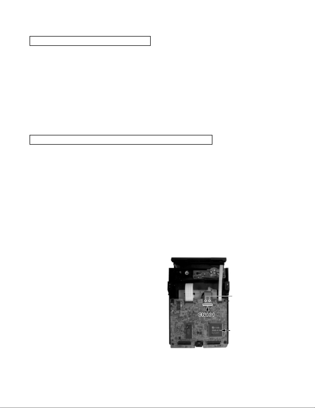
3. After removing the flexible wire from the connector (CN101),
short-circuit the flexible wire by the metal clip.
4. Short-circuit the laser diode by soldering the land which is provided
at the center of the flexible wire for the pickup.
After completing the repair, remove the solder
to open the circuit.
Servo control
board
Short circuit
Please refer to "Fig.4" of "Disassembly
method" for details.

XV-S40BK/XV-S42SL/XV-S45GD/XV-S30BK
1-6
Disassembly method
<Main body>
Removing the top cover (see Fig.1)
Removing the mechanism assembly
(see Fig.2,3)
Removing the servo control board
(see Fig.4)
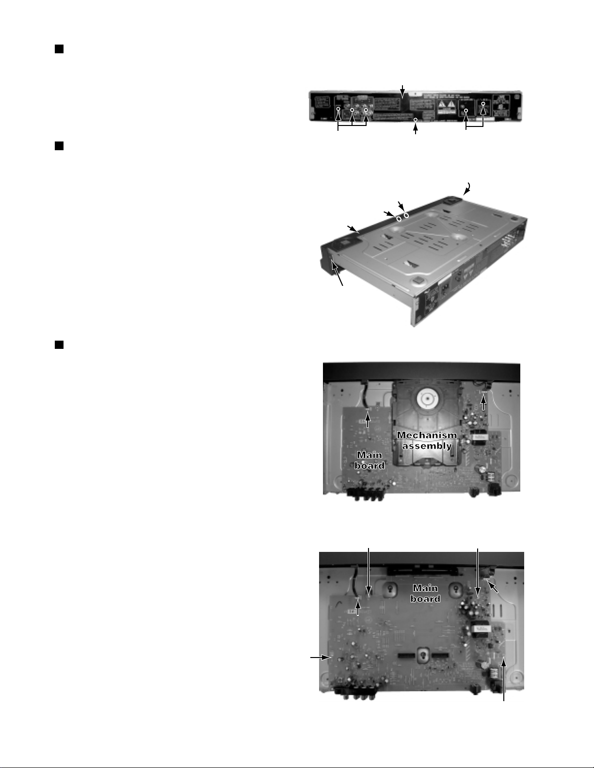
1.Remove the two screws Aattaching the top cover
on both sides of the body.
2.Remove the three screws Battaching the top cover
on the back of the body.
3.Remove the top cover from the body by lifting the
rear part of the top cover.
ATTENTION: Do not break the front panel tab
fitted to the top cover.
* Prior to performing the following procedure, remove
the top cover.
* There is no need to remove the front panel assembly.
1.Remove the three screws Cattaching the mechanism
assembly on the bottom chassis.
2.The servo control board is removed from the connector
CN961 and CN701 connected with the main board
respectively.
3.Remove the mechanism assembly by lifting the rear part
of the mechanism assembly.
* Prior to performing the following procedure, remove
the top cover and mechanism assembly.
1.Disconnect the card wire from connector CN201 and
CN202 on the servo control board respectively.
2.Disconnect the flexible wire from connector CN101
on the servo control board from pick-up.
ATTENTION
At this time, please extract the wire after short-circuited
of two places on the wire in part awith solder.
Please remove the solder two places of part aafter
connecting the wire with CN101 when reassembling.
3.Two places in hook bare removed, the servo control board
is lifted, and it is removed.
*Please remove lug wire when you do not remove
the mechanism assembly easily.
A x 2
B
B
B
Fig.1
CC
C
CN703
CN702
Fig.2
CN701 CN961
Servo control
board
Main board
Mechanism
assembly
Fig.3
Hook b Hook b
Servo control
board
Fig.4
Lug wire
XV-S40BK/XV-S42SL/XV-S45GD/XV-S30BK
1-7
Removing the rear panel (see Fig.5)
Removing the front panel assembly
(see Fig.6,7)
Removing the main board (see Fig.8)
*Prior to performing the following procedure, remove
the top cover.
1.Remove the six screws Dattaching the rear panel
on the back of the body.
* Prior to performing the following procedure, remove
the top cover.
* There is no need to remove the mechanism assembly.
1.Remove the one screw Eattaching the front panel
assembly on the bottom chassis.
2.Disconnect the wire from CN702 and CN703 on the
main board respectively.
3.Hook cand dare removed respectively, and the front
panel assembly is removed.
* Prior to performing the following procedure, remove
the top cover, mechanism assembly and rear panel.
1.Disconnect the wire from CN702 and CN703 on the
main board respectively.
2.Remove the four screws Fattaching the main board
on the bottom chassis.
DDD
Rear panel
Fig.5
E
Hook c
Hook d
Hook d
Front panel
assembly
Fig.6
CN703
CN702
Fig.7
CN703
CN702
Fig.8
F
F
F
F

XV-S40BK/XV-S42SL/XV-S45GD/XV-S30BK
1-8
Remove the four screws Aattaching the clamper
assembly.
Move the clamper in the direction of the arrow to
release the two joints aon both sides.
1.
2.
<Loading assembly section>
Removing the clamper assembly
(See Fig.1)
Prior to performing the following procedure, remove
the clamper assembly.
Push bof the slide cam into the slot on the left side
of the loading base until it stops.
Draw out the tray toward the front.
1.
2.
Removing the tray (See Fig.2 and 3)
When reattaching, fit the clamper to
the two joints a.
ATTENTION:
Before reattaching the tray, slide the
part cof the slide cam to the right as
shown in Fig.3.
ATTENTION:
Joint a
Joint a
AA
A
A
Fig.1
Fig.2
Fig.3
Push
b
Tray
Clamper base
Part c
Slide cam
XV-S40BK/XV-S42SL/XV-S45GD/XV-S30BK
1-9
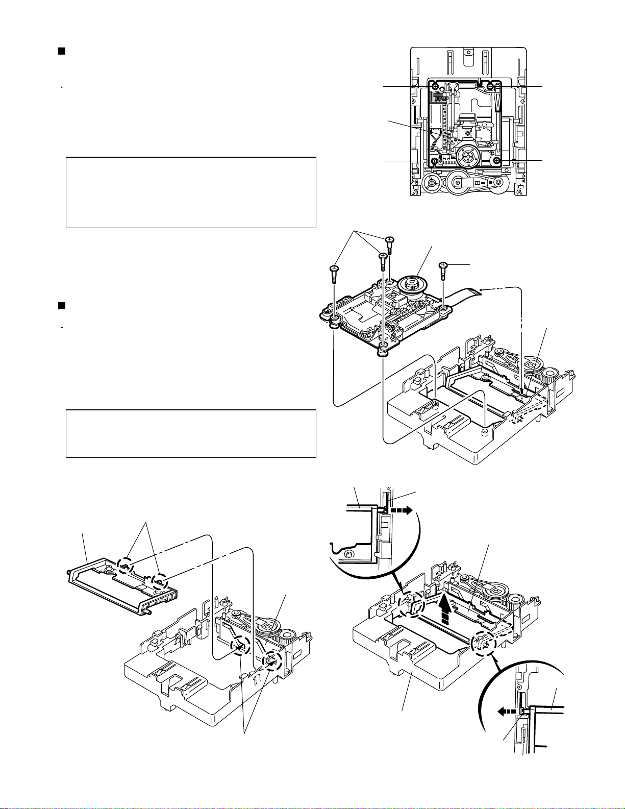
Prior to performing the following procedure, remove
the clamper assembly and the tray.
Remove the four screws Battaching the traverse
mechanism assembly.
1.
Removing the traverse mechanism
assembly (See Fig.4 and 5)
Before reattaching the traverse
mechanism assembly, pass the card
wire extending from the spindle motor
board through the notch dof the
elevator.
ATTENTION:
Prior to performing the following procedure, remove
the clamper assembly, the tray and the traverse
mechanism assembly.
Extend each bar einside of the loading base
outward and detach the elevator shaft.
1.
Removing the elevator (See Fig.6 and 7)
When reattaching, first fit the two
shafts on the front of the elevator to
the slots fof the slide cam.
ATTENTION:
Fig.4
Fig.5
Fig.6Fig.7
BB
B
BB
B
Traverse mechanism
assembly
B
BB
Traverse mechanism assembly
Elevator
Notch d
Elevator
Elevator
Elevator
e
e
Loading base
Elevator
Shafts
Slide cam
Slots f

XV-S40BK/XV-S42SL/XV-S45GD/XV-S30BK
1-10
Prior to performing the following procedure, remove
the clamper assembly, the tray, the traverse
mechanism assembly and the elevator.
Remove the belt from the pulley.
Remove the screw Cattaching the motor assembly.
Turn over the body and remove the screw D
attaching the motor assembly.
Release the two tabs gretaining the motor board.
1.
2.
3.
4.
Removing the motor assembly
(See Fig.8 and 9)
Fig.8
Fig.9
C
Motor assembly
Belt
Loading base
Motor assembly
D
Tabs g
Altri manuali per XV-S40BK
5
Questo manuale è adatto per i seguenti modelli
3
Indice
Altri manuali JVC Lettore DVD


JVC
JVC XV-521BK Manuale utente

JVC
JVC KV-DV50 Guida

JVC
JVC LVT2008-001B Manuale utente

JVC
JVC XV-S403SG Manuale utente

JVC
JVC HR-J470MS Manuale utente

JVC
JVC XV-D9000 Manuale utente

JVC
JVC XV-N320BAG2 Manuale utente

JVC
JVC XV-S302SL Manuale

JVC
JVC XV-N650BAG Guida per l'amministratore

JVC
JVC XV-S5OOBK Manuale utente


