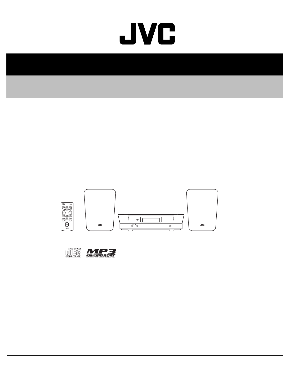
JVC UX-N1SJ Manuale utente

SERVICE MANUAL
COPYRIGHT © 2006 Victor Company of Japan, Limited No.MB514
2006/3
MICRO COMPONENT SYSTEM
MB51420063
UX-N1SJ,UX-N1SC,UX-N1SB,
UX-N1SE,UX-N1SEN,UX-N1SEV,
UX-N1WJ,UX-N1WC,UX-N1WB,
UX-N1WE,UX-N1WEN,UX-N1WEV
Lead free solder used in the board (material : Sn-Ag-Cu, melting point : 219 Centigrade)
TABLE OF CONTENTS
1 PRECAUTION. . . . . . . . . . . . . . . . . . . . . . . . . . . . . . . . . . . . . . . . . . . . . . . . . . . . . . . . . . . . . . . . . . . . . . . . . 1-3
2 SPECIFIC SERVICE INSTRUCTIONS . . . . . . . . . . . . . . . . . . . . . . . . . . . . . . . . . . . . . . . . . . . . . . . . . . . . . . 1-6
3 DISASSEMBLY . . . . . . . . . . . . . . . . . . . . . . . . . . . . . . . . . . . . . . . . . . . . . . . . . . . . . . . . . . . . . . . . . . . . . . . 1-7
4 ADJUSTMENT . . . . . . . . . . . . . . . . . . . . . . . . . . . . . . . . . . . . . . . . . . . . . . . . . . . . . . . . . . . . . . . . . . . . . . . 1-12
5 TROUBLE SHOOTING. . . . . . . . . . . . . . . . . . . . . . . . . . . . . . . . . . . . . . . . . . . . . . . . . . . . . . . . . . . . . . . . . 1-13
CA-UXN1S
for DIGIATLAUDIO PLAYER
IN LINE OUT
SP-UXN1SSP-UXN1S
CA-UXN1W SP-UXN1WSP-UXN1W

1-2 (No.MB514)
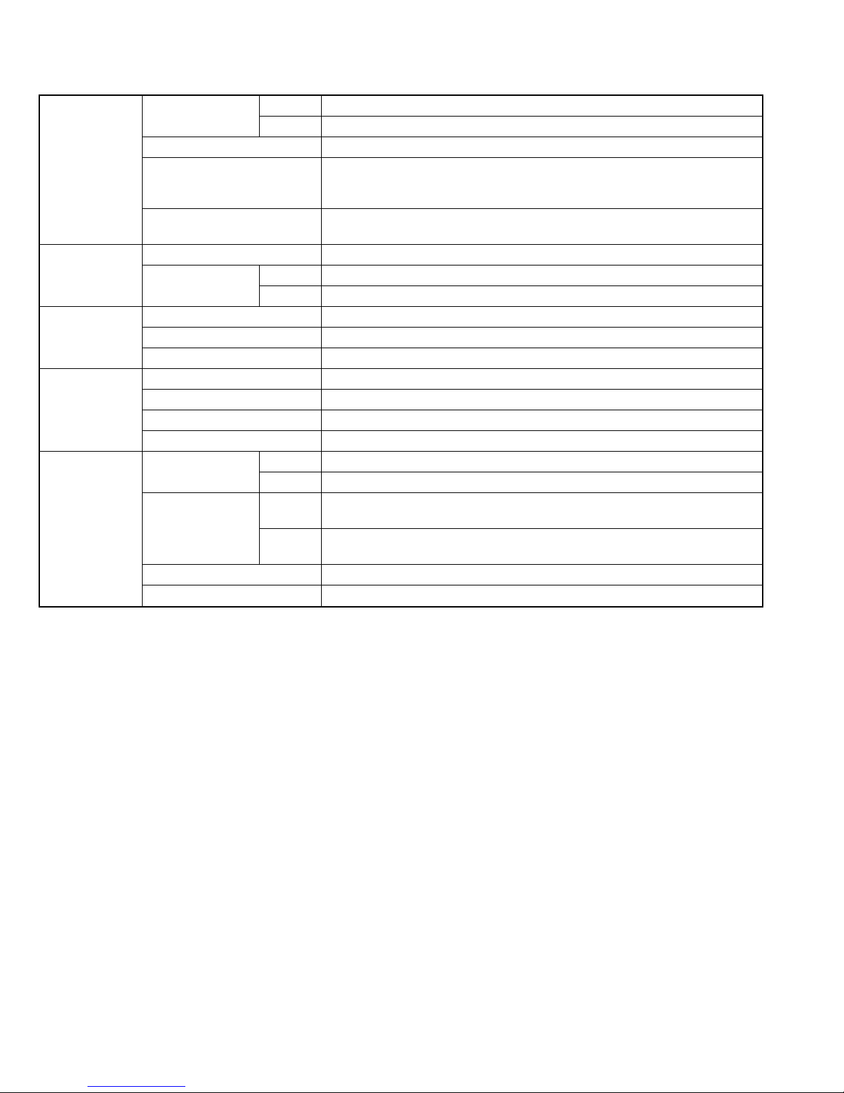
SPECIFICATION
Design and specifications are subject to change without notice.
Amplifier section OUTPUT POWER J,C 13 W (6.5 W + 6.5 W) at 4 Ω(10% THD)
other area 10 W (5 W + 5 W) at 4 Ω(10% THD)
Speakers/Impedance 4 Ω- 16 Ω
Audio Input : LINE IN 500 mV/47 kΩ(at "LINE IN LVL1")
250 mV/47 kΩ(at "LINE IN LVL2")
125 mV/47 kΩ(at "LINE IN LVL3")
Audio output : LINE OUT 1.0 Vrms (10 kΩ) (at "LINE OUT LVL1")
2.0 Vrms (10 kΩ) (at "LINE OUT LVL2")
Tuner section FM Tuning range 87.5 MHz - 108.0 MHz
AM Tuning range J,C 530 kHz - 1 710 kHz
other area 522 kHz - 1 629 kHz
CD player section Dynamic range 88 dB
Signal-to-noise ratio 93 dB
Wow and flutter Immeasurable
Speakers Speaker units 8 cm (3-3/16 inch) cone ×1
Impedance 4 Ω
Dimensions (approx.) (W/H/D) 130 mm ×171 mm ×136 mm (5-1/8 inch ×6-3/4 inch ×5-3/8 inch)
Mass (approx.) 0.75 kg (1.7 lbs) each
General Power requirements J,C AC 120 V , 60 Hz
other area AC 230 V , 50 Hz
Power consumption J,C 21.0 W (POWER ON), 3.5 W (STANDBY mode)
3.0 W or less (SAVE mode)
other area 20.0 W (POWER ON), 3.6 W (STANDBY mode)
3.0 W or less (SAVE mode)
Dimensions (W ×H ×D) 270 mm ×68.5 mm ×203 mm (10-11/16 inch ×2-3/4 inch ×8 inch)
Mass 1.8 kg

(No.MB514)1-3
SECTION 1
PRECAUTION
1.1 Safety Precautions
(1) This design of this product contains special hardware and
many circuits and components specially for safety purpos-
es. For continued protection, no changes should be made
to the original design unless authorized in writing by the
manufacturer. Replacement parts must be identical to
those used in the original circuits. Services should be per-
formed by qualified personnel only.
(2) Alterations of the design or circuitry of the product should
not be made. Any design alterations of the product should
not be made. Any design alterations or additions will void
the manufacturers warranty and will further relieve the
manufacture of responsibility for personal injury or property
damage resulting therefrom.
(3) Many electrical and mechanical parts in the products have
special safety-related characteristics. These characteris-
tics are often not evident from visual inspection nor can the
protection afforded by them necessarily be obtained by us-
ing replacement components rated for higher voltage, watt-
age, etc. Replacement parts which have these special
safety characteristics are identified in the Parts List of Ser-
vice Manual. Electrical components having such features
are identified by shading on the schematics and by ( ) on
the Parts List in the Service Manual. The use of a substitute
replacement which does not have the same safety charac-
teristics as the recommended replacement parts shown in
the Parts List of Service Manual may create shock, fire, or
other hazards.
(4) The leads in the products are routed and dressed with ties,
clamps, tubings, barriers and the like to be separated from
live parts, high temperature parts, moving parts and/or
sharp edges for the prevention of electric shock and fire
hazard. When service is required, the original lead routing
and dress should be observed, and it should be confirmed
that they have been returned to normal, after reassem-
bling.
(5) Leakage shock hazard testing
After reassembling the product, always perform an isola-
tion check on the exposed metal parts of the product (an-
tenna terminals, knobs, metal cabinet, screw heads,
headphone jack, control shafts, etc.) to be sure the product
is safe to operate without danger of electrical shock.Do not
use a line isolation transformer during this check.
• Plug the AC line cord directly into the AC outlet. Using a
"Leakage Current Tester", measure the leakage current
from each exposed metal parts of the cabinet, particular-
ly any exposed metal part having a return path to the
chassis, to a known good earth ground. Any leakage cur-
rent must not exceed 0.5mA AC (r.m.s.).
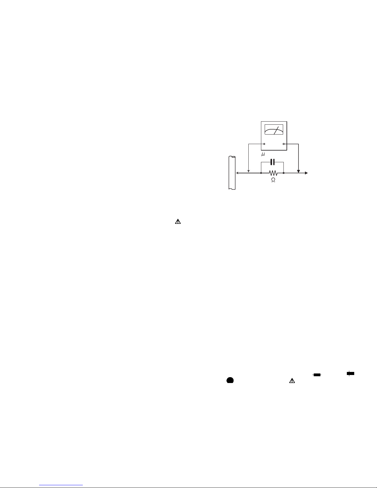
• Alternate check method
Plug the AC line cord directly into the AC outlet. Use an
AC voltmeter having, 1,000Ωper volt or more sensitivity
in the following manner. Connect a 1,500Ω10W resistor
paralleled by a 0.15µF AC-type capacitor between an
exposed metal part and a known good earth ground.
Measure the AC voltage across the resistor with the AC
voltmeter.
Move the resistor connection to each exposed metal
part, particularly any exposed metal part having a return
path to the chassis, and measure the AC voltage across
the resistor. Now, reverse the plug in the AC outlet and
repeat each measurement. Voltage measured any must
not exceed 0.75 V AC (r.m.s.). This corresponds to 0.5
mA AC (r.m.s.).
1.2 Warning
(1) This equipment has been designed and manufactured to
meet international safety standards.
(2) It is the legal responsibility of the repairer to ensure that
these safety standards are maintained.
(3) Repairs must be made in accordance with the relevant
safety standards.
(4) It is essential that safety critical components are replaced
by approved parts.
(5) If mains voltage selector is provided, check setting for local
voltage.
1.3 Caution
Burrs formed during molding may be left over on some parts
of the chassis.
Therefore, pay attention to such burrs in the case of pre-
forming repair of this system.
1.4 Critical parts for safety
In regard with component parts appearing on the silk-screen
printed side (parts side) of the PWB diagrams, the parts that are
printed over with black such as the resistor ( ), diode ( )
and ICP ( ) or identified by the " " mark nearby are critical
for safety. When replacing them, be sure to use the parts of the
same type and rating as specified by the manufacturer.
(This regulation dose not Except the J and C version)
Good earth ground
Place this
probe on
each exposed
metal part.
AC VOLTMETER
(Having 1000
ohms/volts,
or more sensitivity)
1500 10W
0.15 F AC TYPE

1-4 (No.MB514)
1.5 Preventing static electricity
Electrostatic discharge (ESD), which occurs when static electricity stored in the body, fabric, etc. is discharged, can destroy the laser
diode in the traverse unit (optical pickup). Take care to prevent this when performing repairs.
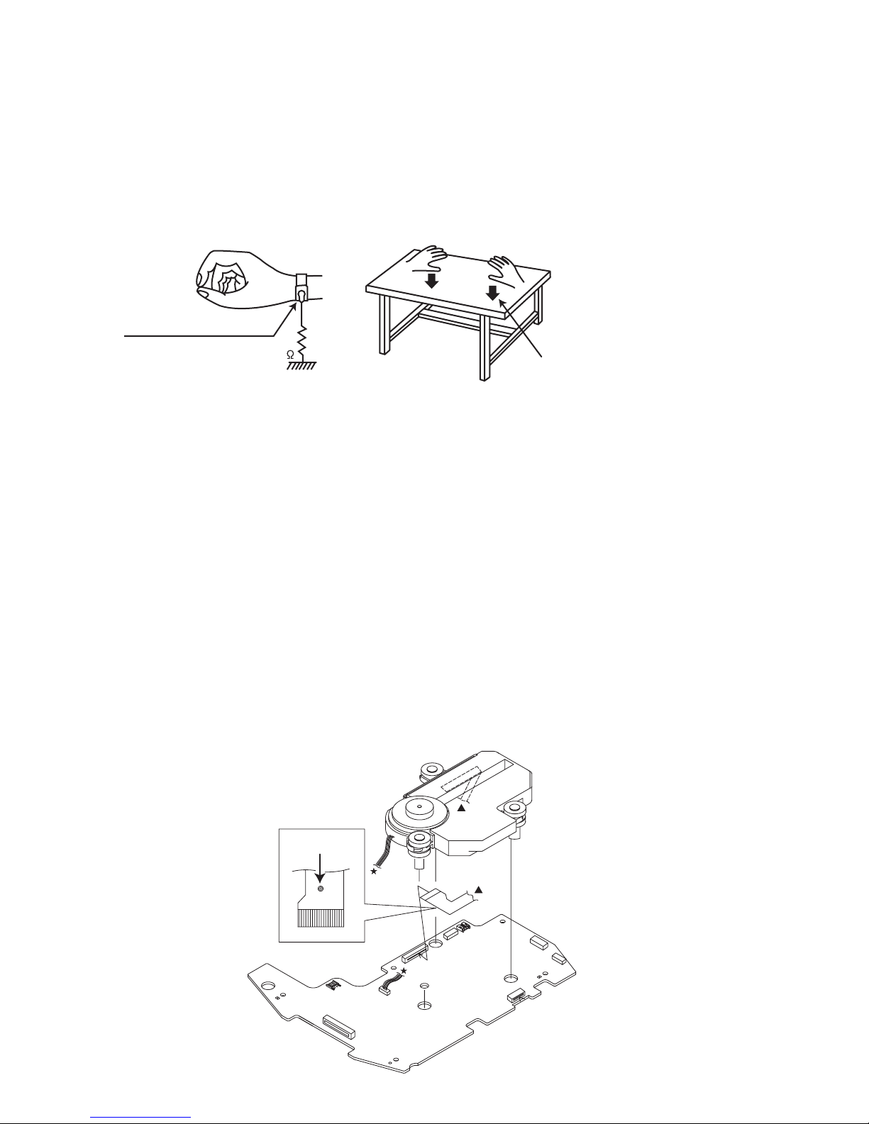
1.5.1 Grounding to prevent damage by static electricity
Static electricity in the work area can destroy the optical pickup (laser diode) in devices such as laser products.
Be careful to use proper grounding in the area where repairs are being performed.
(1) Ground the workbench
Ground the workbench by laying conductive material (such as a conductive sheet) or an iron plate over it before placing the
traverse unit (optical pickup) on it.
(2) Ground yourself
Use an anti-static wrist strap to release any static electricity built up in your body.
(3) Handling the optical pickup
• In order to maintain quality during transport and before installation, both sides of the laser diode on the replacement optical
pickup are shorted. After replacement, return the shorted parts to their original condition.
(Refer to the text.)
• Do not use a tester to check the condition of the laser diode in the optical pickup. The tester's internal power source can easily
destroy the laser diode.
1.6 Handling the traverse unit (optical pickup)
(1) Do not subject the traverse unit (optical pickup) to strong shocks, as it is a sensitive, complex unit.
(2) Cut off the shorted part of the flexible cable using nippers, etc. after replacing the optical pickup. For specific details, refer to the
replacement procedure in the text. Remove the anti-static pin when replacing the traverse unit. Be careful not to take too long a
time when attaching it to the connector.
(3) Handle the flexible cable carefully as it may break when subjected to strong force.
(4) I t is not possible to adjust the semi-fixed resistor that adjusts the laser power. Do not turn it.
1.7 Attention when traverse unit is decomposed
*Please refer to "Disassembly method" in the text for the pickup unit.
• Apply solder to the short land sections before the flexible wire is disconnected from the connecto on the servo board. (If the flexible
wire is disconnected without applying solder, the pickup may be destroyed by static electricity.)
• In the assembly, be sure to remove solder from the short land sections after connecting the flexible wire.
1M
Conductive material
(conductive sheet) or iron palate
(caption)
Anti-static wrist strap
Short land
CN602
CN601

(No.MB514)1-5
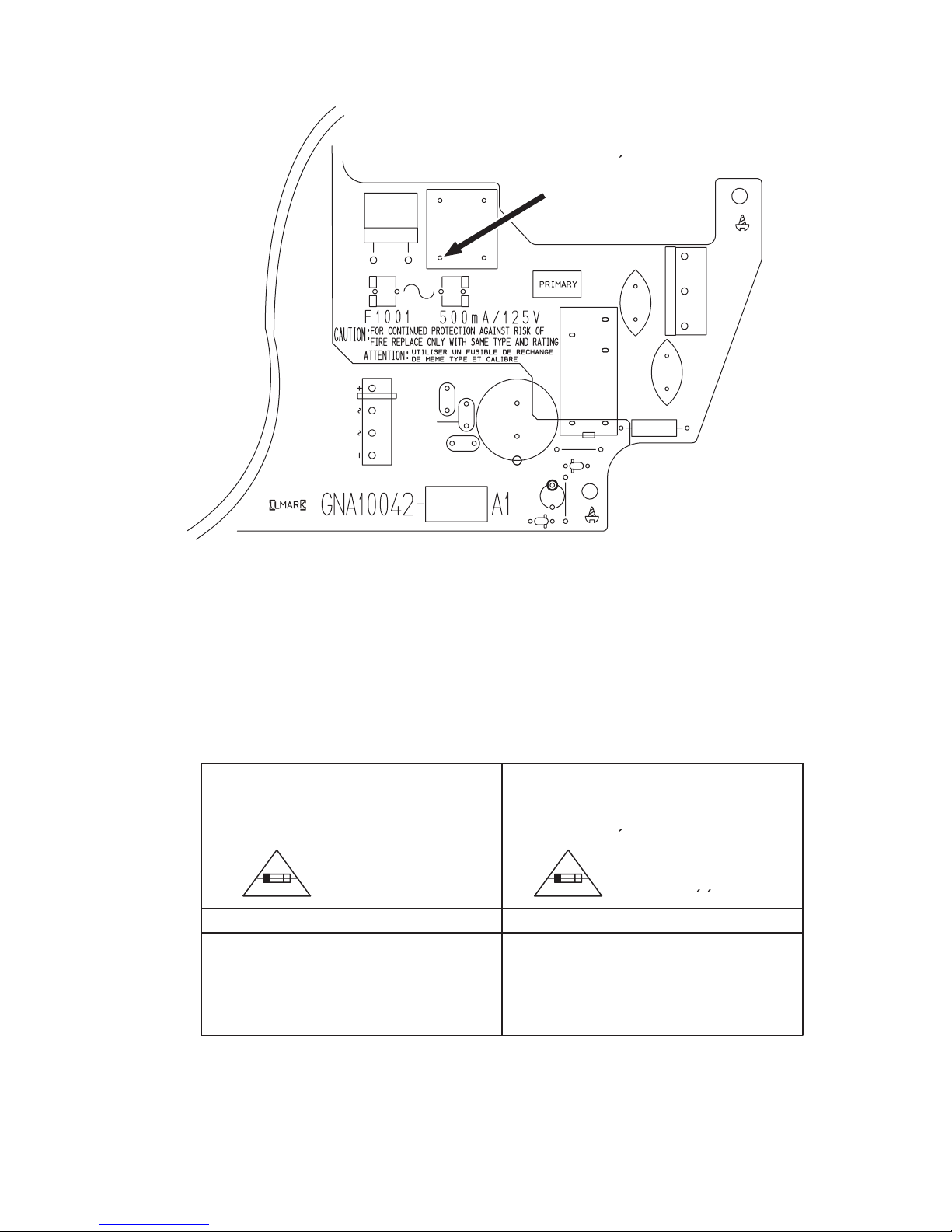
1.8 Importance administering point on the safety
Graphic symbol mark
(This symbol means fast blow type fuse.)
FOR CONTINUED PROTECTION AGAINST RISK
OF FIRE, REPLACE ONLY WITH SAME TYPE
AND RATING OF FUSES ;
should be read as follows ;
F1001 : 500mA 125V
Full Fuse Replacement Marking
FUSE CAUTION
Le symbole graphique (Ce symbole signifie
fusible de type a fusion rapide.)
POUR UNE PROTECTION CONTINUE CONTRE
DES RISQUES D'INCENDIE, REMPLACER
SEULEMENT PAR UN FUSIBLE DU MEME TYPE ;
F1001 : 500mA 125V
Marquage Pour Le Remplacement
Complet De Fusible
PRECAUTIONS SUR LES FUSIBLES
doit etre interprete comme suit ;
^
fast blow type / type a fusion rapide
C1001
C1004
C1006
C1007
C1008
C3301
CN101
CN103
D1001
D1002
LF101
B1317
Z1001Z1011
RY101
R1001
B1319
D1003
C1003

1-6 (No.MB514)
SECTION 2
SPECIFIC SERVICE INSTRUCTIONS
This service manual does not describe SPECIFIC SERVICE INSTRUCTIONS.

(No.MB514)1-7
SECTION 3
DISASSEMBLY
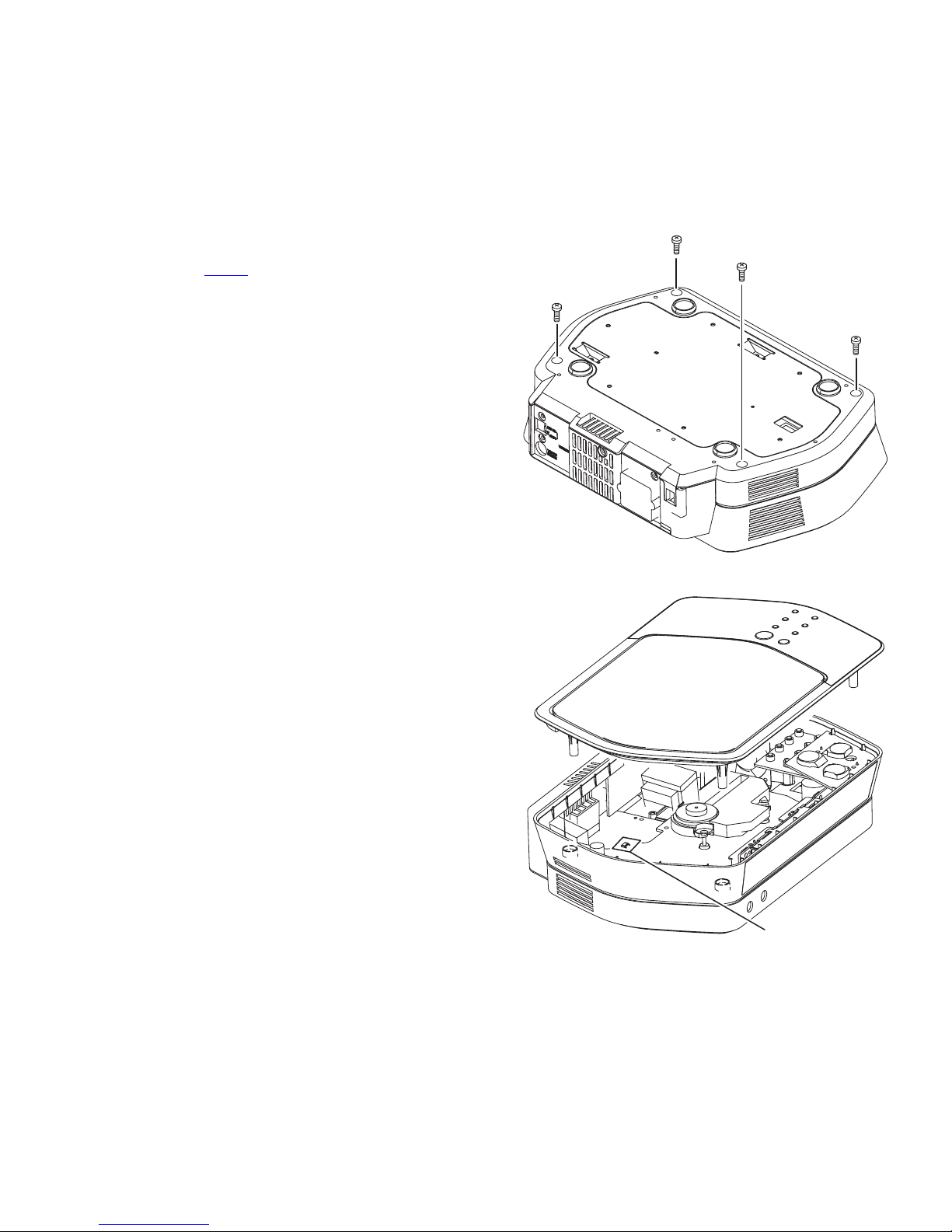
3.1 Main body
3.1.1 Removing the top panel assembly
(See Fig.1 and 2)
(1) Remove the four screws Aattaching the top panel assem-
bly from bottom side. (See Fig.1)
(2) Turn over the main body, lift up the top cover assembly and
disconnect the connector wire from moor motor connected
to connector CN511 of CD and micon board. (See Fig.2)
Fig.1
Fig.2
A
A
A
A
CN511

1-8 (No.MB514)
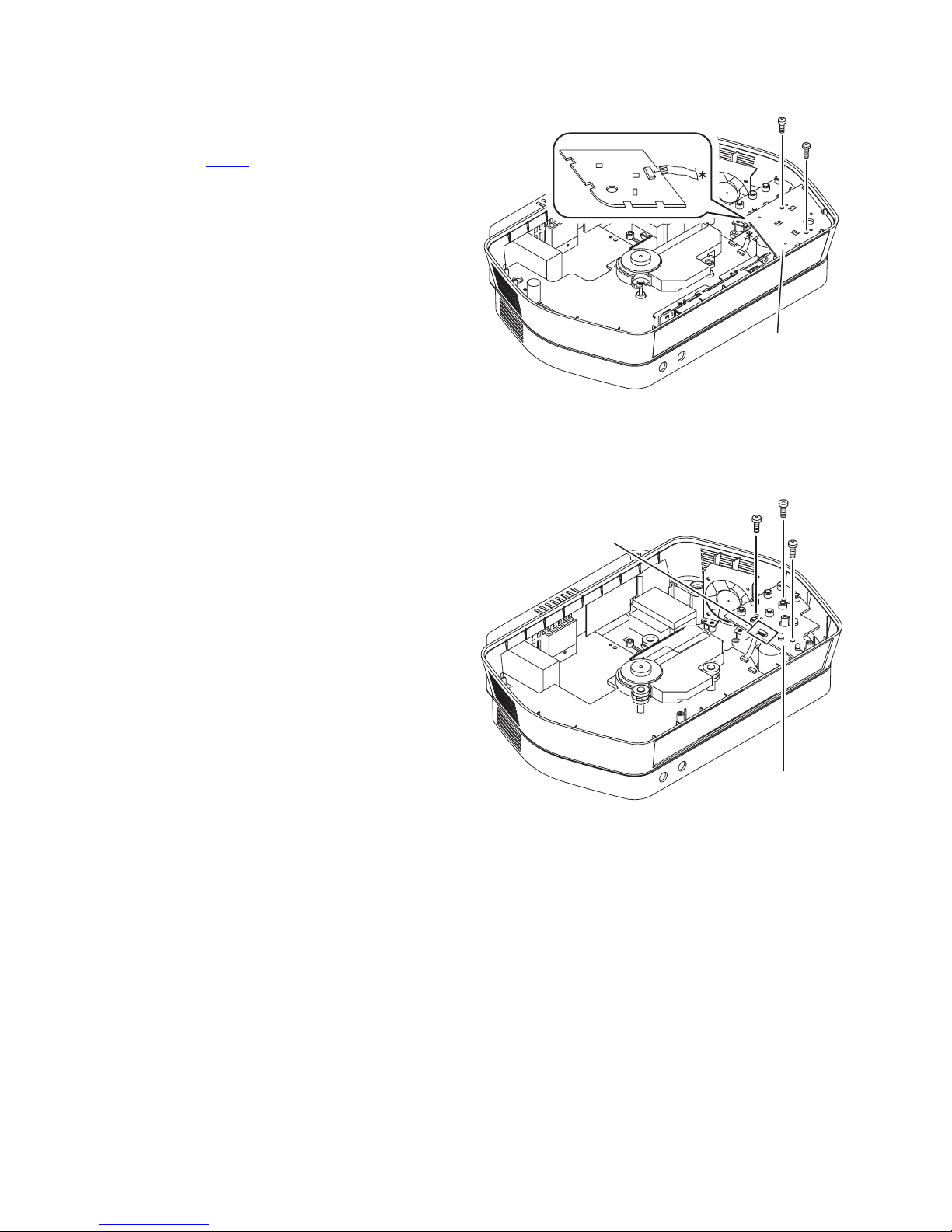
3.1.2 Removing the touch board
(See Fig.3)
(1) Take out the three lenses from touch board.
(2) Remove the two screws Battaching the touch board.
(3) Disconnect the card wire from CD and micon board con-
nected to connector CN431 of touch board.
Fig.3
3.1.3 Removing the touch switch and LED board
(See Fig.4)
(1) Removed the three screws Cattaching the touch switch
and LED board.
(2) Disconnect the card wire from CD and micon board con-
nected to connector CN251 of touch switch and LED
board.
Fig.4
Touch board
CN431
Touch switch &
LED board
CN251
C
C
C

(No.MB514)1-9
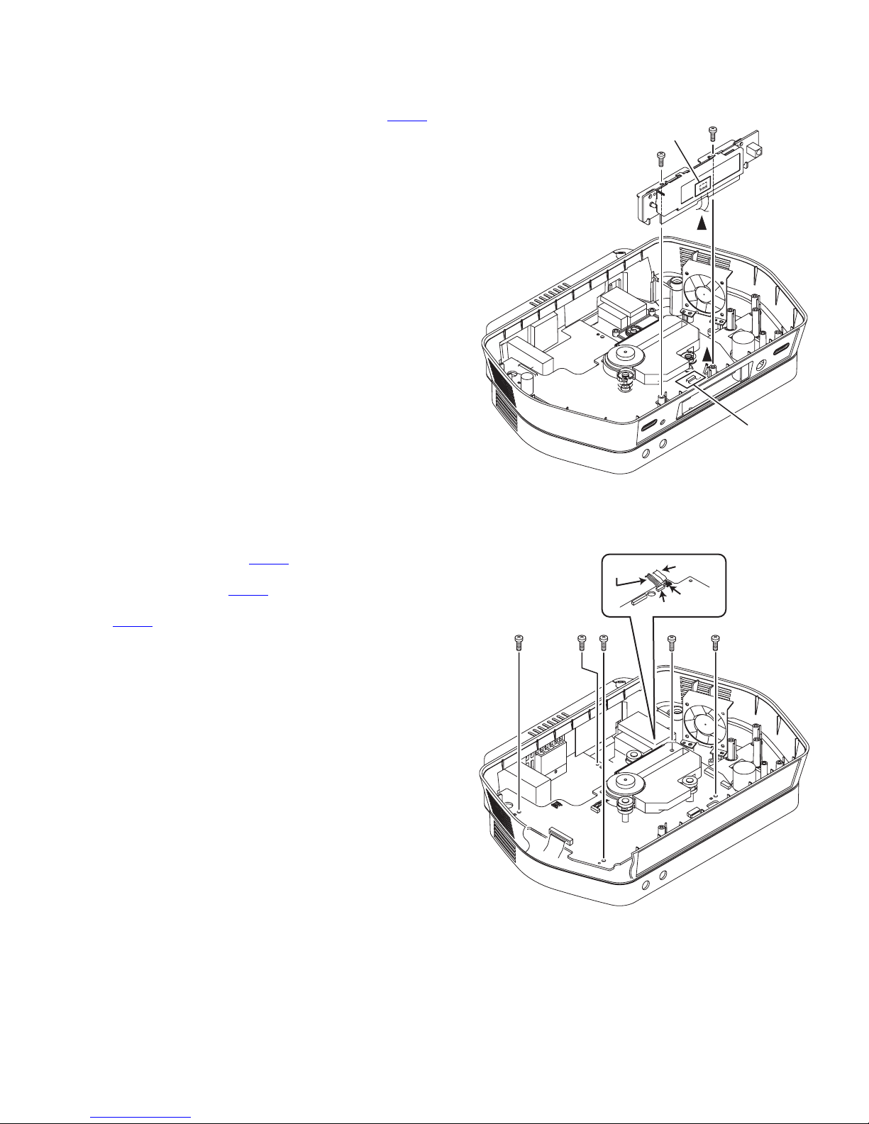
3.1.4 Removing the LCD board
(See Fig.5)
(1) Remove the two screws Dattaching the LCD board.
(2) Disconnect the card wire connected to connector CN701 of
CD and micon board.
Fig.5
3.1.5 Removing the CD and micon board
(See Fig.6)
(1) Disconnect the connector wire from power and audio board
connected to connector CN707 of CD and micon board.
(2) Disconnect the card wire from power and audio board con-
nected to connector CN703 of CD and micon board.
(3) Disconnect the connector wire connected to connector
CN314 of power and audio board.
(4) Remove the five screws Eattaching the CD and micon
board.
Fig.6
CN221
CN701
D
D
CN704
CN316
CN314
CN707
CN703
Ex5

1-10 (No.MB514)
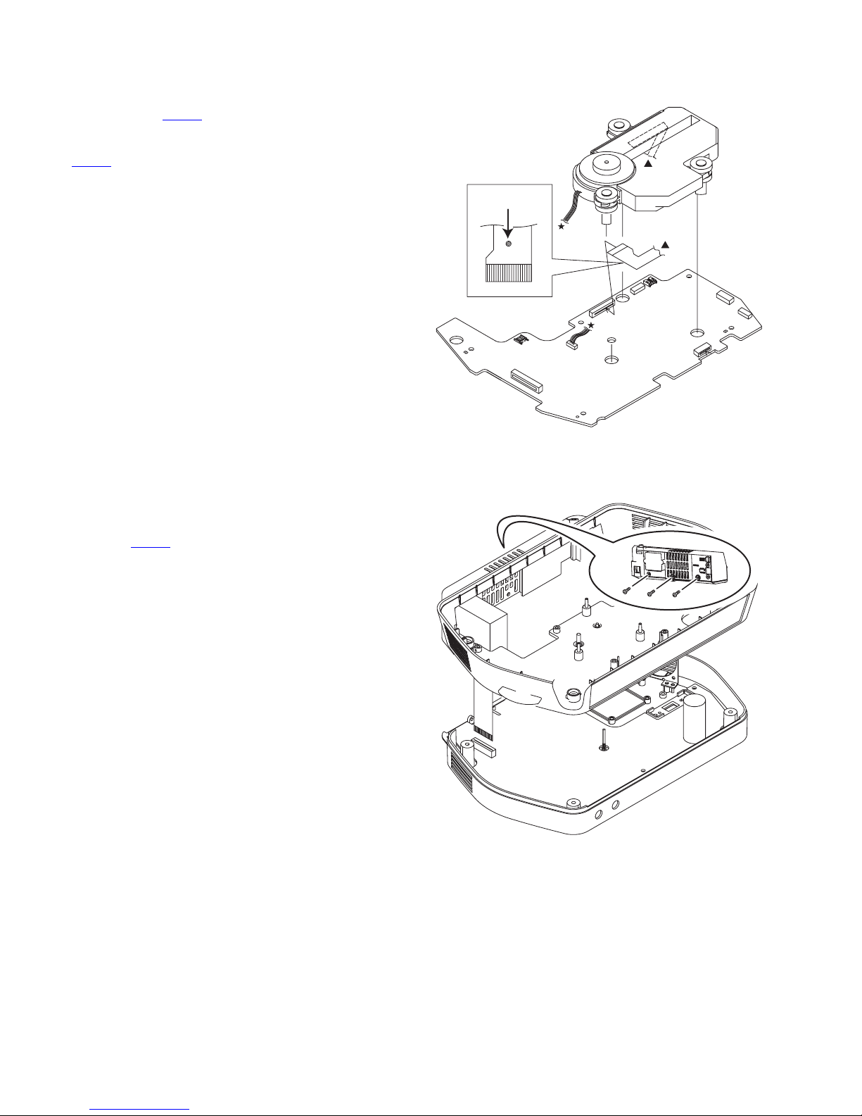
3.1.6 Removing the CD mechanism assembly
(See Fig.7)
(1) Disconnect the connector wire from spindle motor connect-
ed to connector CN602 of CD and micon board.
(2) Solder to short land section of flexible wire and then dis-
connect the flexible wire of pickup connected to connector
CN601 of CD and micon board.
Caution:
• Solder the short land section at the flexible wire of pickup be-
fore disconnecting the flexible wire from the connector on
the CD and micon board. If the flexible wire is disconnected
without attaching solders, the pickup may be destroyed by
static electricity.
• When attaching the CD pickup, be sure to remove solders
from the short land section after connecting the flexible wire
to the connector on the CD and micon board.
Fig.7
3.1.7 Removing the side panel assembly
(See Fig.8)
(1) Remove the three screws Fattaching the side panel as-
sembly from back side.
(2) Disconnect the card wire from tuner pack connected to
connector CN911 of power and audio board.
Fig.8
Short land
CN602
CN601
CN911
F
Questo manuale è adatto per i seguenti modelli
11
Indice
Altri manuali JVC Impianto stereo

JVC
JVC UX-G5 Manuale utente

JVC
JVC NX-PS1 Manuale utente

JVC
JVC PC-X290 Manuale utente

JVC
JVC SP-EXA10 Manuale utente

JVC
JVC CA-UXG500V Manuale utente

JVC
JVC UXG28 - UX G28 Micro System Manuale utente

JVC
JVC RA-P30W Manuale utente

JVC
JVC NX-T5 Manuale utente

JVC
JVC 0303MWMMDWJEM Manuale utente

JVC
JVC UX-A70MDR Manuale utente

JVC
JVC LVT0059-001A Manuale utente

JVC
JVC UX-J51 Manuale utente

JVC
JVC UX-N1WJ Manuale utente

JVC
JVC UX-V9RMD Manuale utente

JVC
JVC UX-QD70SUB Manuale utente

JVC
JVC SP-PCX290 Manuale utente

JVC
JVC HX-Z3 Guida per l'amministratore

JVC
JVC FS-P400 Manuale utente

JVC
JVC UX-T77 Manuale utente

JVC
JVC CA-UXA52R Manuale utente