
JYTEK PCIe/PXIe-6301 Series Manuale utente

PCIe/PXIe-6301 Series
24 bits Temperature Input
Module for Resistance
Temperature Detector
User Manual
User Manual Version: V1.6
Revision Date: Apr. 18, 2020

Table of Contents
1. Overview............................................................................................1
1.1 Introduction ................................................................................1
1.2 Main Features ............................................................................2
1.3 Abbreviations .............................................................................2
2. Hardware Specifications..................................................................3
2.1 System Diagram.........................................................................3
2.2 Sensor Connection.....................................................................4
2.3 Analog Input Performance .........................................................7
2.4 PFI..............................................................................................7
2.5 Front Panel conections and Pinouts ..........................................8
3. Performance Test............................................................................11
3.1 Resistance measurement noise...............................................11
3.2 Temperature measurement accuracy......................................18
3.2.1 Temperature measurement accuracy(4-wire)................18
3.2.2 Temperature measurement accuracy(3-wire)................19
3.2.3 Temperature measurement accuracy(3-wire)................19
3.3 Temperature measurement stability ........................................21
3.4 RDC (Resistance-digital conversion) accuracy........................22
4. Software...........................................................................................23
4.1 System Requirements..............................................................23
4.2 System Software......................................................................23
4.3 C# Programming Language.....................................................24
4.4 PCIe/PXIe-6301 Hardware Driver............................................24
4.5 Install the SeeSharpTools from JYTEK ...................................24
4.6 Running C# Programs in Linux................................................25
5. Operating PCIe/PXIe-6301 Boards ................................................25
5.1 Quick Start ...............................................................................25
5.2 AI Operations ...........................................................................25
5.2.1 Channel Scan Sequence...............................................26
5.2.2 ADC Timing Modes........................................................27
5.2.3 Sampling Rate ...............................................................28
5.3 Conversion of Resistance and Temperature ...........................30
5.4 Trigger Source .........................................................................31
5.4.1 Immediate Trigger..........................................................31
5.4.2 Software Trigger ............................................................31
5.4.3 External analog trigger...................................................31

5.4.4 External digital trigger....................................................33
5.5 Trigger Mode............................................................................33
5.5.1 Start Trigger...................................................................33
5.5.2 Reference Trigger..........................................................34
5.5.3 Re-Trigger......................................................................34
6. Calibration .......................................................................................36
7. Using PCIe/PXIe-6301 in Other Software......................................37
7.1 Python......................................................................................37
7.2 C++ ..........................................................................................37
7.3 LabVIEW..................................................................................37
8. Appendix..........................................................................................38
9. About JYTEK...................................................................................40
9.1 JYTEK China............................................................................40
9.2 JYTEK Korea and JYTEK in Other Countries..........................40
9.3 JYTEK Hardware Products......................................................40
9.4 JYTEK Software Platform ........................................................41
9.5 JYTEK Warranty and SupportServices....................................41
10. Statement.......................................................................................42
Figure 1 PCIe/PXIe-6301 System Diagram .....................................3
Figure 2 2-wire RTD connection ......................................................4
Figure 3 3-wire RTD connection ......................................................5
Figure 4 4-wire RTD connection ......................................................6
Figure 5 PXIe/PCIe 6301 Front Panel..............................................8
Figure 6 Resistance Measurement noise (4-wire, Level 0)............11
Figure 7 Resistance Measurement noise (4-wire, Level 1)............12
Figure 8 Resistance Measurement noise (4-wire, Level 2)............12
Figure 9 Resistance Measurement noise (4-wire, Level 3)............13
Figure 10 Resistance Measurement noise (4-wire, Level 4)..........13
Figure 11 Resistance Measurement noise (4-wire, Level 5)..........14
Figure 12 Resistance Measurement noise (3-wire, Level 0)..........14
Figure 13 Resistance Measurement noise (3-wire, Level 1)..........15
Figure 14 Resistance Measurement noise (3-wire, Level 2)..........15
Figure 15 Resistance Measurement noise (3-wire, Level 3)..........16
Figure 16 Resistance Measurement noise (3-wire, Level 4)..........16
Figure 17 Resistance Measurement noise (3-wire, Level 5)..........17
Figure 18 Typical Error (4-wire,100Ω Input)...................................18
Figure 19 Typical Error (4-wire,250Ω Input)...................................18

Figure 20 Typical Error (3-wire,100Ω Input)...................................19
Figure 21 Typical Error (3-wire,250Ω Input)...................................19
Figure 22 Typical Error (2-wire,100Ω Input)...................................20
Figure 23 Typical Error (2-wire,250Ω Input)...................................20
Figure 24 Typical Drift(250 Ω Input)...............................................21
Figure 25 Typical Drift(Different Inputs).........................................21
Figure 26 Typical channel scan sequence.....................................26
Figure 27 Random channel scan sequence ..................................27
Figure 28 A / D conversion and sampling......................................28
Figure 29 Hysteresis comparator...................................................32
Figure 30 Window comparator.......................................................32
Figure 31 Rising and falling edges of digital signals......................33
Figure 32 Start trigger....................................................................33
Figure 33 Reference trigger...........................................................34
Figure 34 Re-Trigger......................................................................35
Table 1 PCIe/PXIe-6301 Channel Group.........................................1
Table 2 6301 on different buses.......................................................3
Table 3 Analog Input Performance ..................................................7
Table 4 PFI Specification .................................................................7
Table 5 Pinouts for “4-wire mode” configuration (supports 2-wire, 3-
wire or 4-wire RTD)...................................................................9
Table 6 Pinouts for “ 3-wire mode “ configuration (supports 2-wire, 3-
wire RTD)................................................................................10
Table 7 Resistance Measurement noise........................................11
Table 8 Temperature measurement accuracy (4-wire)..................18
Table 9 Temperature measurement accuracy(3-wire)...................19
Table 10 Temperature measurement accuracy(2-wire).................20
Table 11 Temperature measurement stability ...............................21
Table 12 RDC (Resistance-digital conbersion) accuracy ..............22
Table 13 Supported Linux Versions...............................................23
Table 14 A/D conversion time at different speed levels.................28
Table 15 ADC Timing Modes and maximum aggregate sampling rate
................................................................................................29

PCIe/PXIe-6301 Series | jytek.com | 1
1.Overview
This chapter presents the information how to use this manual and how to
operate the module if you are already familiar with Microsoft Visual Studio
and C# programming language.
1.1 Introduction
JYTEK PCIe/PXIe-6301 is a high-resolution temperature measurement
module designed for PT100 RTD sensor.
PCIe/PXIe-6301 supports two wiring topologies, “4-wire mode” and “3-
wire mode”, which can be selected by software.
In “4-wire mode”, each channel can support 2-wire, 3-wire or 4-wire RTD
configuration for a total of 20 channels;
In “3-wire mode”, each channel can support 2-wire or 3-wire RTD
configuration for a total of 32 channels.
PCIe/PXIe-6301 can measure maximum resistance of 400 Ω, to cover
the full range of RTD sensor PT100, with the maximum sampling rate of
up to 800 samples per second.
The PCIe/PXIe-6301 supports a variety of acquisition trigger modes such
as software and external, and can generate trigger signals such as start
and window. All trigger signals are routed through PFI or PXI chassis
backplane.
PCIe/PXIe-6301 module channel grouping is shown in Table 1.
Table 1 PCIe/PXIe-6301 Channel Group
Wiring topology ADC Channels
ADC 0 Ch0, Ch1, Ch2, Ch3, Ch4
ADC 1 Ch5, Ch6, Ch7, Ch8, Ch9
ADC 2 Ch10, Ch11, Ch12, Ch13, Ch14
ADC 3 Ch15, Ch16, Ch17, Ch18, Ch19
ADC 0 Ch0, Ch1, Ch2, Ch3, Ch4, Ch5, Ch6, Ch7
ADC 1 Ch8, Ch9, Ch10, Ch11, Ch12, Ch13, Ch14, Ch15
ADC 2 Ch16, Ch17, Ch18, Ch19, Ch20, Ch21, Ch22, Ch23
ADC 3 Ch24, Ch25, Ch26, Ch27, Ch28, Ch29, Ch30, Ch31
4-wire mode
3-wire mode

PCIe/PXIe-6301 Series | jytek.com | 2
1.2 Main Features
⚫32 channels (3-wire mode), 20 channels (4-wire mode)
⚫24 bits ADC resolution
⚫-200 °C --+850 °C temperature measurement range (using PT100
thermistor sensor)
⚫0 ~ 400 Ω range
⚫The balance line resistance compensation is provided when the
three wire thermal resistance sensor is input
⚫128M sample onboard FIFO buffer for analog input
⚫DMA for analog input
⚫Provide resistance or temperature measurement value
⚫Analog/Digital/Software Trigger
1.3 Abbreviations
AI: Analog Input
ADC: Analog to Digital Converter
PFI: Programmable Function Interface
RTD: Resistance Temperature Detector
Ex+: Positive terminal of current Excitation
Ex-: Ngative terminal of current Excitation
RDC: Resistance-to-Digital Converter
OS: Operating System

PCIe/PXIe-6301 Series | jytek.com | 3
2.Hardware Specifications
The PCIe/PXIe-6301 is one of the family of temperature input module,
which can run on PCIe, PXIe, TXI (Thuderbolt) and USB buses (coming
soon). PCIe/PXIe-6301 on different buses are shown in Table 2.
Table 2 6301 on different buses
2.1 System Diagram
Multiplexer
Multiplexer
Multiplexer
Multiplexer
ADC0
ADC1
ADC2
ADC3
DDR FPGA
Front-panlel Interface
Ch0-Ch4/Ch0-Ch7
Ch5-Ch9/Ch8-Ch15
Ch10-Ch14/Ch16-Ch23
Ch15-Ch19/Ch24-Ch31
Figure 1 PCIe/PXIe-6301 System Diagram
Figure 1 shows the system diagram of the PCIe/PXIe-6301. The system
is mainly composed of ADC, DDR and FPGA control modules. The
FPGA-based driver code provides a stable and efficient PCIe / PXIe /
USB interface. PCIe/PXIe-6301 uses four ADCs at the same time. Each
ADC is responsible for the measurement of one channel (5 or 8) and
selects one of the channels through the multiplexer.
6301 Model PCIe PXIe TXI USB
6301 aaaa

PCIe/PXIe-6301 Series | jytek.com | 4
2.2 Sensor Connection
PCIe/PXIe-6301 can support 2-wire, 3-wire or 4-wire RTD connection at
the same time. The wiring configuration used by each channel can be
independently configured by software.
2-wire RTD connection
When using a 2-wire RTD configuration, user needs to connect the
negative terminal of current excitation (Ex-) to the AI- terminal as shown
in Figure 2. Due to the presence of lead wires resistance, this type of
connection may introduce large measurement errors, which are related
to the material and material of the lead wire. This type of wiring is not
suitable for high precision temperature measurement needs.
Figure 2 2-wire RTD connection

PCIe/PXIe-6301 Series | jytek.com | 5
3-wire RTD connection
In a 3-wire RTD configuration, AI+ terminal will output a precision current
excitation, 500 µA to RTD sensor and flow back through the Ex- terminal
and AI- terminal as shown in Figure 3 . Since the voltage generated by
the RTD connecting the AI+ terminal and the voltage connected to the AI-
terminal will cancel each other, this connection can effectively eliminate
the influence of the lead wire resistance, but in practical applications, the
resistance of the two lead wires is difficult to match completely, so there
will still be a certain degree of mismatch error.
Figure 3 3-wire RTD connection
PCIe/PXIe-6301 Series | jytek.com | 6
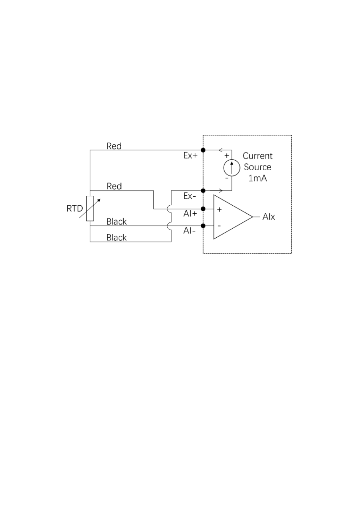
4-wire RTD connection
1
In a 4-wire configuration, the Ex+ terminal will output an current excitation,
1000 µA and flows back through the Ex- terminal and AI- terminal as
shown in Figure 4. Since the current loop and voltage measuring circuit
of the lead wire are independently, so will not introduce errors due to lead
wire resistance.
Figure 4 4-wire RTD connection
1
If you need to use a 4-wire configuration, you must configure the channel topology to a “4-wire mode”
when configuring the acquisition task. In this case, the PCIe/PXIe-6301 provides a total of 20 channels. If
you do not need to use a 4-wire configuration, you can configure the acquisition task to a “3-wire mode”,
in which case the PCIe/PXIe-6301 provides a total of 32 channels.
Indice
Altri manuali JYTEK Hardware per computer

JYTEK
JYTEK USB-62405 Manuale utente

JYTEK
JYTEK NuDAQ PCI-69222 Manuale utente

JYTEK
JYTEK USB-62401 Manuale utente

JYTEK
JYTEK 6743X Series Manuale utente

JYTEK
JYTEK PCIe-5111 Manuale utente

JYTEK
JYTEK JY-5110 Series Manuale utente

JYTEK
JYTEK PCIe-6301 Series Manuale utente

JYTEK
JYTEK PCI-69524 Manuale utente

JYTEK
JYTEK PCIe-68638 Series Manuale utente

JYTEK
JYTEK PCIe-68560 Manuale utente
Manuali Hardware per computer popolari di altre marche

EMC2
EMC2 VNX Series Manuale del proprietario

Panasonic
Panasonic DV0PM20105 Manuale utente

Mitsubishi Electric
Mitsubishi Electric Q81BD-J61BT11 Manuale utente

Gigabyte
Gigabyte B660M DS3H AX DDR4 Manuale utente

Raidon
Raidon iT2300 Manuale utente

National Instruments
National Instruments PXI-8186 Manuale utente


