Kallista P50035 Manuale utente

Installation Guide
Cast Iron
Bath Whirlpool
P50035
1019455-2-E

Important Information
WARNING: When using electrical products, basic precautions should always be followed,
including the following:
DANGER: Risk of electric shock. Connect only to circuits protected by a Ground-Fault
Circuit-Interrupter (GFCI)*.
WARNING: Risk of electric shock. A qualified electrician should make all electrical connections.
WARNING: Risk of electric shock. Disconnect power before servicing.
WARNING: Risk of injury or property damage. Please read all instructions thoroughly before
beginning installation, including the following requirements.
*Outside North America, this device may be known as a Residual Current Device (RCD).
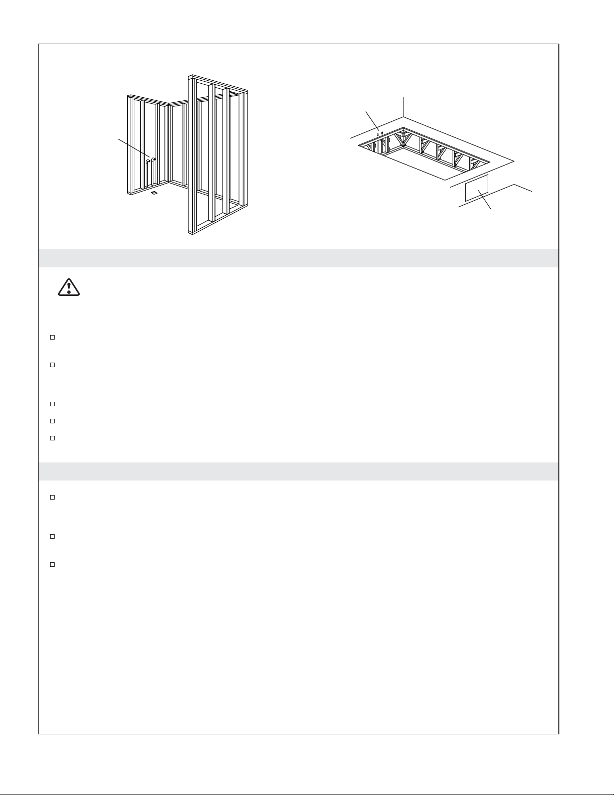
NOTICE: Follow all local plumbing and electrical codes.
Building materials and wiring should be routed away from the pump body and other heat-producing
components of the unit.
Install in a manner that permits access for servicing of all critical components.
A pressure wire connector marked “Earth/Ground” is provided within the wiring compartment. To reduce
the risk of electric shock, connect this connector to the grounding terminal of your electric service or supply
panel with copper wire equivalent in size to the circuit conductor supplying this equipment.
Pressure wire connectors are provided on the exterior of the junction box or control within this unit to permit
connection of a bonding conductor between this unit and all other exposed metal in the vicinity, as needed to
comply with local requirements.
Grounding is required. The unit should be installed by a qualified service representative, and grounded.
Product Information
Electrical Requirements
The installation must have a Class A Ground-Fault Circuit-Interrupter (GFCI)*. The GFCI protects against
line-to-ground shock hazard. Use a 208 - 240 V, 20 A, 50/60 Hz dedicated service for the whirlpool.
*Outside North America, this device may be known as a Residual Current Device (RCD).
Product Notices
WARNING: Unauthorized modification may cause unsafe operation and poor performance of
the whirlpool. Do not relocate the whirlpool pump, or make other modifications to the whirlpool
system, as this could adversely affect the performance and safe operation of the whirlpool. Kallista
shall not be liable under its warranty or otherwise for personal injury or damage caused by any
such unauthorized modification.
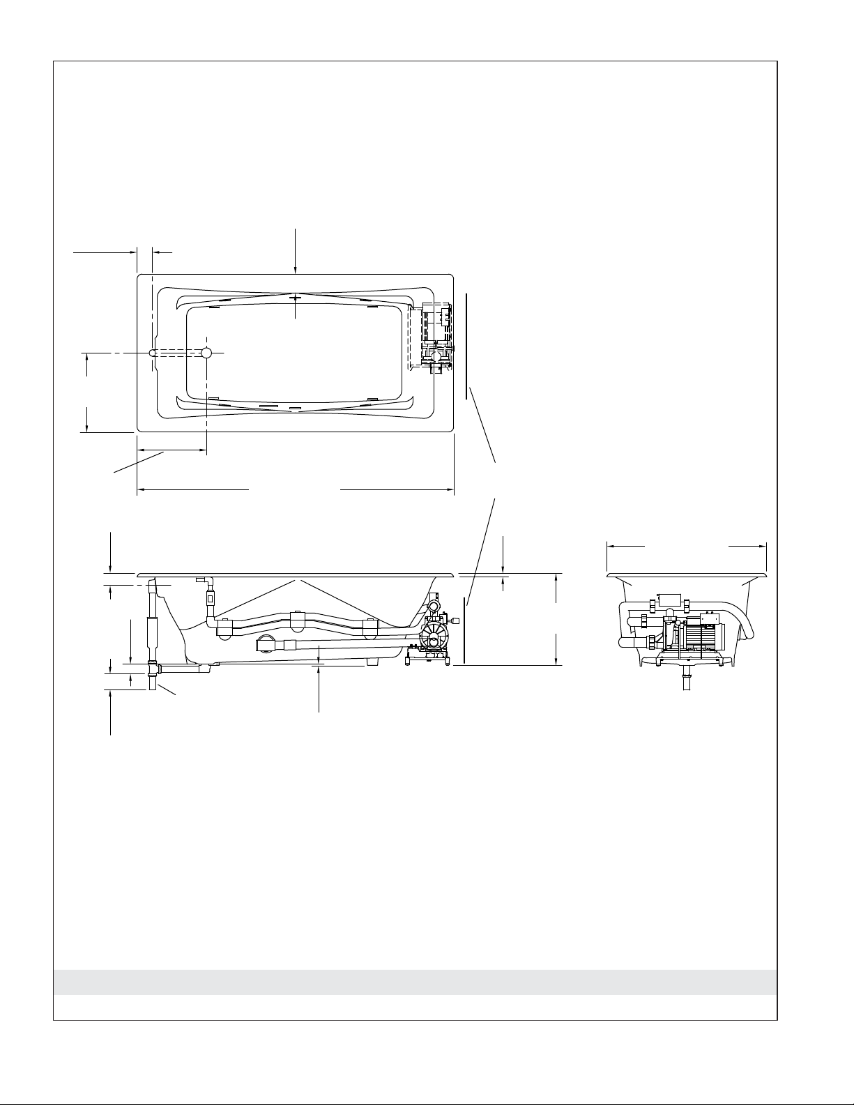
Features
″-H2″Series: Components include a pump, heater, control, Flexjet whirlpool jets, illuminated switch (user
keypad) and remote.
The whirlpool pump and piping are factory-assembled.
1019455-2-E 2 Kallista

Product Information (cont.)
Connections and Service Access
Before installation, ensure proper access to the final connections.
NOTICE: Provide generous, unrestricted service access to the pump. You must provide access for
servicing the pump and controls. The access must be located immediately next to the pump. Study the
roughing-in information for your whirlpool model.
Table of Contents
Important Information .............................................................. 2
Product Information ............................................................... 2
Electrical Requirements .......................................................... 2
Product Notices ................................................................ 2
Features ..................................................................... 2
Connections and Service Access ................................................... 3
Tools and Materials ............................................................... 3
Before You Begin ................................................................. 4
Roughing-In Dimensions ........................................................... 5
Prepare the Site - Concrete Construction ............................................... 6
Prepare the Site - Wood Construction .................................................. 7
Prepare the Whirlpool ............................................................. 7
Install the Whirlpool ............................................................... 8
Cut the Pump Banding Straps ....................................................... 8
Install the Plumbing ............................................................... 8
Make Electrical Connections ......................................................... 9
Test Run the Whirlpool ............................................................ 10
Complete the Finished Wall/Deck .................................................... 11
Complete the Concrete Installation ................................................... 11
Clean-Up After Installation ......................................................... 11
Confirm Proper Operation .......................................................... 12
Operating Sequence ............................................................. 12
Remote Control Operation ......................................................... 13
Troubleshooting Procedures ........................................................ 13
Tools and Materials
Silicone Sealant
Tin Snips
Plus:
• Conventional Woodworking Tools
and Materials
• Drop Cloth
• Metal Shims
• 2x4s
Kallista 3 1019455-2-E

Before You Begin
WARNING: Risk of personal injury. Your cast iron whirlpool is extremely heavy. Obtain sufficient
help to carefully lift and move it.
CAUTION: Risk of product damage. Do not lift the whirlpool by the piping or pump, or use the
piping or pump for structural support of the whirlpool.
CAUTION: Risk of product damage. Do not support the whirlpool by the rim.
This whirlpool is intended for drop-in or alcove installation, depending upon the model chosen.
Inspect the whirlpool for damage before you begin installation.
You must install this whirlpool to an adequately supported, level subfloor.
Kallista reserves the right to make revisions in the design of products without notice, as specified in
the Price Book.
1019455-2-E 4 Kallista

1. Roughing-In Dimensions
36" (914 mm)
20-7/8"
(530 mm)
Pump/Control Access
24" (610 mm) W x 14" (356 mm) H
3"
(76 mm)
1-1/2" OD
2-7/8"
(73 mm)
2-1/2"
(64 mm)
72" (1829 mm)
1/4"
(6 mm)
4-3/8"
(111 mm)
3-1/2"
(89 mm)
18"
(457 mm)
15-5/8"
(397 mm)
3/4"
(19 mm)
Kallista 5 1019455-2-E

2. Prepare the Site - Concrete Construction
CAUTION: Risk of product damage. Do not support the whirlpool by the rim.
NOTICE: Adequate floor support must be provided. Floor supports under the whirlpool must provide for
a minimum of 1800 lbs (816 kg).
Make sure the flooring offers adequate support for your whirlpool, and verify that the subfloor is
flat and level.
This whirlpool may be installed next to the wall or in an island installation. An island installation
requires a four side surround. In both instances, make sure the deck is supported by brick or
concrete.
Install an access panel to allow the pump to be serviced.
Construct brick or concrete supports.
Provide a 1/16″(2 mm) gap between the whirlpool rim and the concrete or brick framing. Frame
the floor, or construct a frame for a raised installation, in accordance with the roughing-in section of
this guide.
Position the plumbing according to the roughing-in information. Cap the supplies, and check for
leaks.
Bath
Tile
Approved
Tile Backing
Tile
Brick
Approved
Tile Backing
Typical
Access
Panel
Whirlpool may be installed
next to the wall or as an
island installation.
Install an access panel to allow
the pump to be serviced.
Brick
1/16"
(2 mm)
1019455-2-E 6 Kallista

3. Prepare the Site - Wood Construction
CAUTION: Risk of product damage. Do not support the whirlpool by the rim.
NOTICE: Adequate floor support must be provided. Consult the roughing-in information for your
whirlpool for specific floor loading requirements.
Make sure the flooring offers adequate support for your whirlpool, and verify that the subfloor is
flat and level.
The whirlpool may be used in a drop-in or alcove installation. Construct 2x4 stud framing designed
for your particular installation. Frame the floor, or construct a frame for a raised installation in
accordance with the roughing-in information packed with the whirlpool.
Use the roughing-in information to carefully lay out and cut the rough deck material.
Install an access panel to allow the pump to be serviced.
Position the plumbing according to the roughing-in information. Cap the supplies, and check for
leaks.
4. Prepare the Whirlpool
We recommend a tiling-in bead for straight-rimmed whirlpools, if one or more sides of the
whirlpool contact a wall. This bead prevents water from seeping between the whirlpool rim and the
wall. Follow the instructions packed with the tiling-in bead to install the bead now.
Install the drain to the whirlpool according to the drain manufacturer’s instructions. Do not connect
the trap at this time.
Position a clean drop cloth or similar material in the bottom of the whirlpool. Be careful not to
scratch the surface of the whirlpool.
Access
Panel
Construct according
to the product
dimensions.
Construct 2x4
stud framing
according to the
product dimensions.
Alcove Drop-In
Rough
Plumbing
Rough
Plumbing
Kallista 7 1019455-2-E

5. Install the Whirlpool
WARNING: Risk of personal injury. This cast iron whirlpool is extremely heavy. Obtain sufficient
help to carefully lift and move it.
CAUTION: Risk of product damage. Do not lift the whirlpool by the piping or pump, or use the
piping or pump for structural support of the whirlpool.
CAUTION: Risk of product damage. Do not support the whirlpool by the rim.
Carefully move the whirlpool into position. Insert the drain tailpiece into the trap.
Level the whirlpool by fitting metal shims under the whirlpool feet as needed. Check for level along
the top of the whirlpool, and across the drain side. If the feet are not accessible from the back or
side, move the whirlpool in and out of position to shim it properly. Make sure the whirlpool is
resting on all four feet.
6. Cut the Pump Banding Straps
IMPORTANT! This step is necessary to make your whirlpool operate more quietly.
Use tin snips to cut the two pump banding straps from the whirlpool pump.
NOTE: Do not raise the pump higher than it was before you cut the pump banding straps. If the pump is
raised too high, it will not prime properly. Make sure the rubber isolation feet are in place.
To minimize whirlpool noise and vibration, be sure the pump is not in direct contact with the
whirlpool after the pump banding straps are cut. The pump control contains rubber isolation feet to
reduce pump noise.
7. Install the Plumbing
CAUTION: Risk of property damage. Ensure a watertight seal on the whirlpool drain.
Connect the drain to the trap according to the drain manufacturer’s instructions.
NOTICE: An access panel will simplify future maintenance.
Install the faucet valving according to the faucet manufacturer’s instructions. Do not install the
faucet trim until instructed. Open the hot and cold water supplies, and check the supply
connections for leakage.
Run water into the whirlpool, and check the drain connections for leakage.
Level by fitting metal shims
under the feet.
Pump
Wiring
Harness
Control
Cut the pump banding straps.
Rubber Isolation Feet
1019455-2-E 8 Kallista

8. Make Electrical Connections
NOTE: The product model number is printed on a label on the pump side of the whirlpool bath. This
label also identifies the electrical rating of the product. All whirlpools come equipped with a wiring
junction box and are designed to operate between 208 VAC and 240 VAC at either 50 Hz or 60 Hz.
WARNING: Risk of electrical shock. Make sure the power has been disconnected before
performing the following procedures. Refer to the “Important Information” section.
WARNING: Risk of electrical shock. Connect the pump to a properly grounded Ground-Fault
Circuit-Interrupter (GFCI)*. This will provide additional protection against line-to-ground shock
hazard. A 208-240 V, 20 A, 50/60 Hz dedicated circuit is required.
IMPORTANT! The load neutral is not used. There should be no connection to the load neutral terminal
on the Ground-Fault Circuit-Interrupter (GFCI) breaker. The green wire with the yellow stripe is the
equipment ground and needs to be connected to the neutral bus in the main circuit breaker box.
*Outside North America, this device may be known as a Residual Current Device (RCD).
The whirlpool bath control and system have been pre-wired at the factory. A qualified electrician
should make a routine service connection to the junction box.
Connect service to the junction box. The junction box contains blue, brown, and green with a yellow
stripe colored wires.
Follow local electrical codes. Bond in accordance with national and local codes.
A wiring harness has been pre-wired at the factory, allowing communication between the keypad,
all features, and the control. No additional wiring is required, but ensure that all wires are securely
fastened.
Bond in accordance with nation and local codes.
Open bonding lugs are located at the top of the
junction box.
Heater (models may vary) T-Style (shown)
or Inline (not shown) Wiring Harness
Junction Box
Control
120/240 VAC
Source
N
120 V
Neutral Bus
(In Breaker Box)
L1 L2
120 V
240 V
*Equipment Ground
*Line Neutral
(White Curly
Wire)
Field Wiring
(From Junction B
to GFCI Breaker)
Electrician to provide
suitable strain relief.
Brown (L2)
From
Control
Ground
(Green with
Yellow Stripes)
Wire Connector
Blue (L1)
240 V
*L1
*L2
No Connection
(Load Neutral)
*Connections to be Made
at the Circuit Breaker
Breaker Box
Typical Two-Pole
Circuit Breaker
with GFCI
Typical Wiring Connection for North America
Pump Electrical Cord
Heater Electrical Cord
Wire Connectors
Kallista 9 1019455-2-E

Make Electrical Connections (cont.)
NOTE: Your wiring harness included an antenna for the optional remote control. Do not alter or damage
this antenna during installation.
9. Test Run the Whirlpool
Check all electrical connections.
Make sure all union connections to the pumps and heater are securely hand tightened.
Verify that the pump banding straps have been cut, and that the pump controls are resting directly
on the subfloor. Ensure that the rubber isolation feet are in place.
Turn electrical power to the whirlpool on.
Fill the whirlpool to a level at least 2″(50 mm) above the top of the highest jet.
Operate the whirlpool for 5 minutes (refer to the “Operating Sequence” section) and check all
whirlpool piping connections, on the back side, for leaks.
Turn on each of the whirlpool features and verify proper function. Check for any water leakage on
the whirlpool’s back side.
For additional information on whirlpool operation, see “Confirm Proper Operation” section.
1019455-2-E 10 Kallista
Altri manuali per P50035
1
Questo manuale è adatto per i seguenti modelli
1
Indice
Altri manuali Kallista Vasca
Manuali Vasca popolari di altre marche

Lyons
Lyons Elite ETLxx663219 Series Manuale utente

Woodbridge
Woodbridge BJ500 Istruzioni per il montaggio

Whirlpool
Whirlpool Ariel ARL-702 Manuale utente

TEIKO
TEIKO EXCELLENT DUO Manuale utente

American Standard
American Standard Colony 5-1/2' x 32" Manuale utente

American Standard
American Standard 3052OD.X0X Guida rapida


