Kanardia Indu Variometer Manuale utente

INDU VARIOMETER
Manual
Kanardia d.o.o.
February 2020
©
Kanardia d.o.o.
Revision 1.1


Variometer — Manual
Contact Information
Publisher and producer:
Kanardia d.o.o.
Lopata 24a
SI-3000
Slovenia
Tel: +386 40 360 512
Email: info@kanardia.eu
A lot of useful and recent information can be also found on the In-
ternet. See http://www.kanardia.eu for more details.
Copyright
This document is published under the Creative Commons, Attribution-
ShareAlike 3.0 Unported licence. Full license is available on http://
creativecommons.org/licenses/by-sa/3.0/legalcode web page
and a bit more human readable summary is given on
http://creativecommons.org/licenses/by-sa/3.0/. In short, the
license gives you right to copy, reproduce and modify this document
if:
you cite Kanardia d.o.o. as the author of the original work,
you distribute the resulting work only under the same or similar
license to this one.
Credits
This document was written using TeTeX (L
A
T
EX) based document
creation system using Kile running on Linux operating system. Most
1
©
Kanardia 2015 - 2020

Variometer — Manual
of the figures were drawn using Open Office Draw and Inkscape ap-
plications. Photos and scanned material was processed using Gimp.
Sam2p was used to convert pictures into eps format. All docu-
ment sources are freely available on request under the licence men-
tioned above and can be obtained by email. Please send requests to
info@kanardia.eu.
Revision History
The following table shows the revision history of this document.
Rev. Date Description
1.0 Oct 2015 Initial release
1.1 Feb 2020 Revision
2
©
Kanardia 2015 - 2020

Variometer — Manual CONTENTS
Contents
1 Introduction 4
1.1 General Description . . . . . . . . . . . . . . . . . . . 4
1.2 Technical Specification . . . . . . . . . . . . . . . . . 4
1.3 Options ......................... 5
1.3.1 Display ..................... 5
2 Installation 7
2.1 Mounting Dimensions . . . . . . . . . . . . . . . . . . 7
2.2 Connections....................... 7
2.2.1 Static Pressure - Pst .............. 7
2.2.2 CAN Bus - CAN ................. 8
2.2.3 Illumination . . . . . . . . . . . . . . . . . . . 9
2.2.4 Power - POWER .................. 10
3 Maintenance & Repair 10
4 Sensor Calibration 11
4.1 Calibration Procedure . . . . . . . . . . . . . . . . . 11
4.2 Pressure Altitude Calculation . . . . . . . . . . . . . 11
4.3 Altitude Derivative . . . . . . . . . . . . . . . . . . . 12
5 Limited Conditions 12
5.1 Warranty ........................ 13
5.2 TSO Information . . . . . . . . . . . . . . . . . . . . 15
3
©
Kanardia 2015 - 2020

Variometer — Manual 1. Introduction
1 Introduction
First of all, we would like to thank you for purchasing our device.
Indu variometer is an electronic device, which mimics classical vari-
ometer construction and combines it with the state of the art elec-
tronics. This results in the best of both worlds; a perfect and intuitive
analogue reading combined with high precision of modern electronics.
This manual describes the technical description of the unit, installa-
tion and operation.
CAUTION: Indu Variometer is not TSO approved as a flight
instrument.
1.1 General Description
The variometer is an electromechanical device. It consist of high
precision electronic barometric sensor, which provides static pressure
information in digital form. The electronics reads the pressure sensor
and numerically calculates the altitude change. The result drives
stepper motor turning a needle. The calculated rate of change is also
shown on a colour LCD display. When connected to a CAN bus the
variometer outputs the vertical speed information. Analog scale is
divided lineary with a zero speed on the left side. An optional dim
knob can be connected to the device and it is used to adjust the
brightness of the screen.
1.2 Technical Specification
Table 1 shows some basic technical specification of Indu variometer.
4
©
Kanardia 2015 - 2020

Variometer — Manual 1.3 Options
Description Value
Weight 57 mm: 150 g
80 mm: 200 g
Size (with connectors) 57 mm: 60 x 60 x 66 mm
80 mm: 82 x 82 x 66 mm
Panel hole (standard fit) 80 mm (3.15 inch)
57 mm (2.25 inch)
Altitude range -500 to 15000 m, (-1500 to 45000 feet)
Operational voltage 8 to 32 V
Power consumption 1.2 W
Current 100 mA at 12 V, 50 mA at 24 V
Operating temperature -30 ◦Cto +85 ◦C
Humidity 30 % -90 %, non condensing
Barometric sensor 24 bit, 10-1200 hPa, 20 cm resolution
Communication CAN bus, 29 bit header, 500 kbit,
Kanardia protocol
Table 1: Basic technical specifications.
1.3 Options
The instrument is available in two different sizes, different scale units
and different scale ranges. The scale units and range must be speci-
fied at the time of order.
The variometer is available in meters per second and feet per minute
units. The standard range is ±10 m/s or ±2000 fpm.
Different units and range is also possible with additional charges.
1.3.1 Display
Standard LCD display layout displays two values: Vario on top of
the screen and flight time on the bottom.
5
©
Kanardia 2015 - 2020

Variometer — Manual 1.3 Options
(a) 57 mm
(b) 80 mm
Figure 1: Front and side view of the variometer with its principal
dimensions.
If you want a different LCD display layout, you can configure it your-
self with our Customizer desktop application.1This option requires
Kanardia’s Blu device for transfering the configuration from your an-
1Available from April 2020
6
©
Kanardia 2015 - 2020

Variometer — Manual 2. Installation
droid device to your Indu Variometer. Please read our Customizer
Manual for more information.
2 Installation
The Indu variometer requires a standard size 80/57 mm hole in the
instrument panel. The position of the hole must ensure visibility
from the pilot’s perspective.
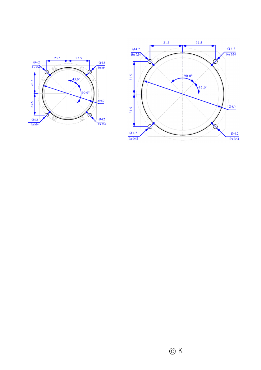
2.1 Mounting Dimensions
The mounting screw holes are located on a circle of 89/65 mm diam-
eter. The instrument is mounted using four screws type M4. To pre-
vent internal stresses, please make sure that the instrument panel is
flat. It is highly recommended that the instrument panel is mounted
using rubber shocks, which reduce the vibrations. Figure 2 illustrates
the panel cutout and mounting holes.
2.2 Connections
Figure 3 illustrates all connections at the back side of the instrument.
2.2.1 Static Pressure - Pst
Indu Variometer must be connected to the static pressure source.
Static pressure source is usually obtained from pressure sources lo-
cated on the fuselage side surfaces or from the static port on the pitot
tube.
Locate the existing tube, cut it at an appropriate place and insert a
T junction. Install a new tube from junction to the instrument.
7
©
Kanardia 2015 - 2020
Variometer — Manual 2.2 Connections
(a) 57 mm
(b) 80 mm
Figure 2: Instrument panel cutout and mounting hole. Note: Figures
are not in scale.
It is highly recommended to keep the static tubing as short as pos-
sible. The tubing must avoid sharp bends and twists. The tubing
must be airtight. Water must not be allowed to enter the tubing.
It is strongly recommended to label each tube before connecting to
Indu Variometer. This will help a lot if you ever have to remove and
re-install the instrument.
2.2.2 CAN Bus - CAN
Connection to the CAN bus is optional and is not required for the
normal operation.
Use standard RJ45 ethernet cable to connect it with other Kanardia
equipment.
When connected to the bus, vaiometer will transmit vertical speed
to other units connected on the bus.
8
©
Kanardia 2015 - 2020
Indice
Altri manuali Kanardia Display avionico

Kanardia
Kanardia INDU COMBO Manuale utente

Kanardia
Kanardia Aetos Manuale utente

Kanardia
Kanardia EMSIS Manuale utente

Kanardia
Kanardia Horis Manuale utente

Kanardia
Kanardia Digi Manuale utente

Kanardia
Kanardia INDU COMBO Manuale utente

Kanardia
Kanardia INDU 80 Manuale utente

Kanardia
Kanardia INDU Airspee Manuale utente
Manuali Display avionico popolari di altre marche

Smart Avionics
Smart Avionics PB-4 Manuale utente

Midcontinent
Midcontinent SAM MD302 Manuale

MGL Avionics
MGL Avionics Stratomaster Maxi Single FF-3 Manuale utente

Garmin
Garmin GI 275 Manuale utente

Mid-Continent Instruments
Mid-Continent Instruments 4300 Series Manuale

Avidyne
Avidyne 700-00182 Series Manuale di servizio


