KATU FTS500 Series Manuale utente

Operating instruction
Integrated flow and temperature sensor
FTS500/FTS520 series
Sensor and controller
Flow pressure temperature level position

01
www.katusensor.com
Safety instruction
Safety instructions are intended to protect users from dangerous situations and/
or prevent material damage.In the operating instructions, the severity of the potential risk
can be indicated by the following signal words:
An imminent danger to the user. Failure to comply may result in fatal injury.
!
danger
An identifiable hazard.
Failure to comply may result in fatal injury and damage to equipment or plant parts.
!
warning
It means a danger.
Failure to comply may result in minor injury and material damage to the switch and
/or plant.
!
caution
Information that is important to the user.
important
Switches must be properly handled in accordance with national or local
regulations for electrical/electronic equipment.
Switches cannot be disposed of with household waste!
Deal with

◇ Cardiac flow range:
liquid: 0.4-350 L/min, depending on the pipe size.
For details about the standard traffic, see the traffic range table.
Gas: Calculated according to specific application
◇ Temperature range: 0~100℃
◇ Accuracy: < ±3.0%F.S (flow rate), < ±1.0℃ (temperature)
◇ Repeatability: < 2.0%
◇ Liquid connection material: Pom/SUS304 (stainless steel)
◇ Pressure rating: 1.6Mpa
◇ Ambient temperature: -10~65℃
◇ Medium temperature: -20~100℃
◇ Process connection:
Thread type: G3/8-G2
◇ Power supply: 18-30VDC
◇ Digital display: OLED LCD screen (1-1/2 ')
◇ Linearization: 5-point linear flow curve
◇ Alarm contact: 2 independent alarm switches, users can set in the full range.
Switching capacity, 24VDC/400mA
◇ Signal output:
Three-wire system 4-20mA, linear relationship with flow, temperature,
arbitrary setting within the user range,
Maximum 500Ω, customized pulse frequency, maximum 1 kHz, user can set,
For example, 1 pulse/L or 1 liter/pulse can be customized RS485
02 www.katusensor.com
Technical parameter

left/reduce key
Enter/Exit/confirm key
Power indicator light Flow indicator
Instantaneous flow value
Signal alarm lamp Signal alarm lamp
Flow: L/min
TEMP: 30.8 ℃
0.0
Flow unit
Real-time temperature value
right/increment key
FTS500 Liquid crystal display
FTS500/FTS520 No display
03
www.katusensor.com
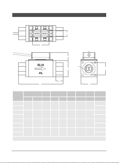
Panel diagram

Selection
code
Process
connection
(G)
Body
height
H (m m )
Mounting
hole
E(mm)
Overall
height
L(m m )
range
L / m in
016A 3 / 8
45*45 32* 3 2 110
2-1 6
016B1/2
040A 1/2
5 - 4 0
040B 3/4
10 0 A 3 / 4
10 - 10 0
100B 1
250A 1-1/4
58* 5 832* 3 1 114 5 0 - 25 0
250B 1-1/2
41.5
G G G
15.0 15.050.0
L
6.0
M12*1 Aviation plug
33.0
R Thread tolerance
to Gauge datum
67.5
H
H
φ4.5
E
4-M4 Depth of teeth 10.0 32.0
04 www.katusensor.com
FTS500 Dimensional drawing
05
www.katusensor.com
FTS520 Dimensional drawing
A
C
E
L
H
H
R/G
ES
B
Type
selection
code
Install Hole position
shell
height ontology height Lock bit
joint
hexagon
flow
range
process
connection
(A) (B) (C) (H)(L) (E) (ES)L/min (R/G)
004A
25mm 15mm 24mm 30*30m
m80mm 17mm 27mm 0.5-4
3/8
004B 1/2
016A
25mm 15mm 24mm 30*30m
m84mm 19mm 27mm 2-16
3/8
016B 1/2
040A
40mm 15mm 20mm 40*40m
m110mm 18mm 30mm 5-40
1/2
040B 3/4
100A
40mm 20mm 20mm 45*45m
m120mm 23mm 41mm 10-100
3/4
100B 1
Effective screw 15m
m

PNP+(4-20mA)
brown
grey
green
pink
blue
red
yellow
white
brown
white
yellow
red
pink
green
grey
blue
1
2
3
4
5
6
7
8
F mA
T mA
T
F
24VDC +
-
NPN+(4-20mA)
1
8
7
6
4
3
2
5
T mA
F mA
F
T
24VDC +
-
Liquid crystal display
4-20mA+P/L
1
2
3
4
5
F mA(flow)
F P(flow)
T mA(temperature)
18-28VDC +
-
No display
1
2
3
4
5
brown
black
blue
white
grey
brown
black
blue
white
grey
Power supply +
Temperature analog
Power supply -
Flow pulse
Flow analog
brown
grey
green
pink
blue
red
yellow
white
1
2
3
4
Power supply +
Flow analog
Temperature analog
5
6
7
8
Power supply -
Temperature switch
Flow switch
06 www.katusensor.com
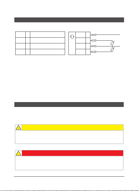
FTS500 Wiring diagram
07
www.katusensor.com
Safety instructions are intended to protect users from dangerous situations and/or
prevent material damage. In the operating instructions, the severity of the potential risk can
be indicated by the following signal words:
install
Switches should only be installed in systems that do not exceed the maximum
pressure Pmax (see type label).Install switches only when power is off
(electrical, hydraulic/pneumatic).
!
danger
Vibration and violent vibration must be avoided during transportation.
Even if the switch housing is not damaged,
Internal components can also break down and cause failure.
!
caution
Analog quantity 4-20mA
brown
black
blue
white
1
2
3
4
F mA(flow)
T mA(temperature)
18-28VDC +
-
1
2
3
4
brown
black
blue
white
Power supply +
Temperature analog quantity
Power supply -
Flow analog
FTS520 Wiring diagram
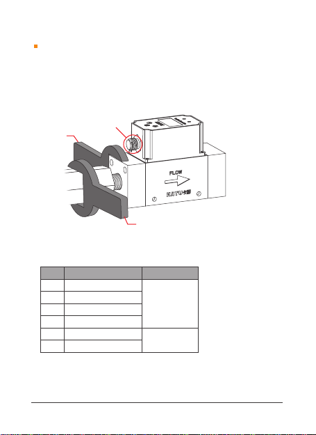
Piping method:
When piping a product, use a wrench to pipe the metal parts (pipe fittings) that
are integrated with the piping part.
If you use a wrench in other parts, the flow switch may be damaged.
In particular, no spanner can be used on the M12 connector.
Otherwise, the connector may be damaged
If the switch is tightened outside the torque range, it may be damaged. If assembled
without a specified tightening torque, it may loosen the joint thread.
Installation of piping:
Please do not let the sealing
tape into the tube.
Piping connection:
Please do not relax and cause
liquid leakage.
Please strictly observe the safe torque value of piping:
Attentional collision
Fixed wrench
Fastening wrench (please refer to torque value)
thread
G 3/8
G 1/2
G 3/4
G 1
G 1-1/4
G 1-1/2
22~24 N·m
28~30 N·m
28~30 N·m
36~38 N·m
40~42 N·m
48~50 N·m
<200N·m
<250N·m
Applicable torque range Torque safe range
08 www.katusensor.com

DN is the gauge gauge unit:mm
15DN 5DN
Sensor upstream
pipeline type Length of front and rear straight pipe section
Concentric contraction
Fully open valve
A 90-degree bend
Two on the same plane
A 90-degree bend
20DN 5DN
25DN 5DN
09
www.katusensor.com
Questo manuale è adatto per i seguenti modelli
1
Indice


