Ki Mobility Tsunami ALX Manuale utente

THIS TECHNICAL MANUAL HAS BEEN DEVELOPED FOR AND
INTENDED TO BE USED BY A QUALIFIED TECHNICIAN
WORKING FOR AN AUTHORIZED KI MOBILITY DEALER.

1
WARNING: Repairs and adjustments not made by a qualified technician working for an
authorized Ki Mobility Dealer can result in poor performance or failure of the device
which may cause serious injury or death.
This technical manual is designed to aid in the different procedures that may be needed for
the Tsunami and Little Wave wheelchairs. This technical manual does not replace, but aids the
owner manual, adjustment guides and instructions. The procedures shown in this technical
manual should only be performed by an Assistive Technology Practitioner (ATP) or clinical
professional trained to do wheelchair repairs, adjustments and retrofits.
Additional information can be found in the Tsunami and Little Wave Owner Manuals. The
owner manuals can be found on the Ki Mobility website.
If you have any questions or concerns about any aspect of this wheelchair, this manual, or the
service provided by us or your retail supplier, please do not hesitate to contact us by
telephone at:
715-254-0991
In writing at:
Ki Mobility
5201 Woodward Drive
Stevens Point, WI 54481
U.S.A
Via email at:
Or via our Authorized EU Representative:
James Leckey Design
19C Ballinderry Road
Lisburn
BT28 2SA
Phone: 0800 318265 (UK) or 1800 626020 (ROI)
www.leckey.com

2
A. Tools................................................................................................................ 3
B. Chair Measurement References...................................................................... 4
C. Caster Mount .................................................................................................. 5
D. Caster Forks and Stems ................................................................................. 6
E. Caster Angle and Squaring ............................................................................. 11
F. Camber Mount Assembly - Tsunami .............................................................. 12
G. Camber Mount Assembly - Little Wave .......................................................... 16
H. Camber Tube and Adapters............................................................................ 18
I. Center of Gravity Adjustment.......................................................................... 19
J. Setting Toe to Zero ......................................................................................... 20
K. Backrest Assembly ......................................................................................... 21
L. Height Adjustable Back Post .......................................................................... 25
M. Fixed Height Back Post .................................................................................. 26
N. Rigid Stroller Handle ....................................................................................... 27
O. Ergo Stroller Handle ........................................................................................ 27
P. Bolt-On Push Handle ...................................................................................... 28
Q. Height Adjustable T-Arm................................................................................. 29
R. Angle Adj. Locking Flip Up Extendable Armrest - Available on Little Wave ... 30
S. Swing Away Armrest ....................................................................................... 31
T. Cane and Crutch Holder ................................................................................. 32
U. Luggage Carrier .............................................................................................. 33
V. Handrim Configurations .................................................................................. 34
W. Handrim Construction..................................................................................... 35
X. Seat Pan.......................................................................................................... 36
Y. Seat Upholstery............................................................................................... 37
Z. Side Guards .................................................................................................... 38
AA. Transit ............................................................................................................. 42
AB. Angle Adjustable Footrest............................................................................... 44
AC. Angle Adjustable Flip Under Footrest ............................................................. 45
AD. High Mount Angle Adjustable Footrest - Available on Tsunami ..................... 46
AE. High Mount Angle Adj. Footrest (10"-14" Wide) ............................................. 47
AF. High Mount Angle Adjustable Footrest (15" - 19" Wide) ................................ 48
AG. High Mount Angle Adjustable Flip Under Footrest ......................................... 49
AH. Little Wave Frame Width................................................................................. 50
AI. Anti-Tips.......................................................................................................... 51
AJ. Little Wave 5th Wheel ..................................................................................... 53
AK. Wheel Locks.................................................................................................... 56
AL.
AM.
AN.
AO.
Table of Contents

3
Tools
Please see the list below to identify the tools needed throughout this tech manual. Always
check tools to ensure the ends are not stripped and that the tool can perform its function
properly without damaging any parts or hardware on the chair.
Tools Needed
• 2.5mm Allen Wrench • Two 8mm Wrenches
• 3mm Allen Wrench • Two 10mm Wrenches
• 4mm Allen Wrench • 13mm Wrench
• 5mm Allen Wrench • 17mm Wrench
• 5.5mm Allen Wrench • 19mm Wrench
• 6mm Allen Wrench • 24mm Wrench
• Utility blade • Phillips Screwdriver
4
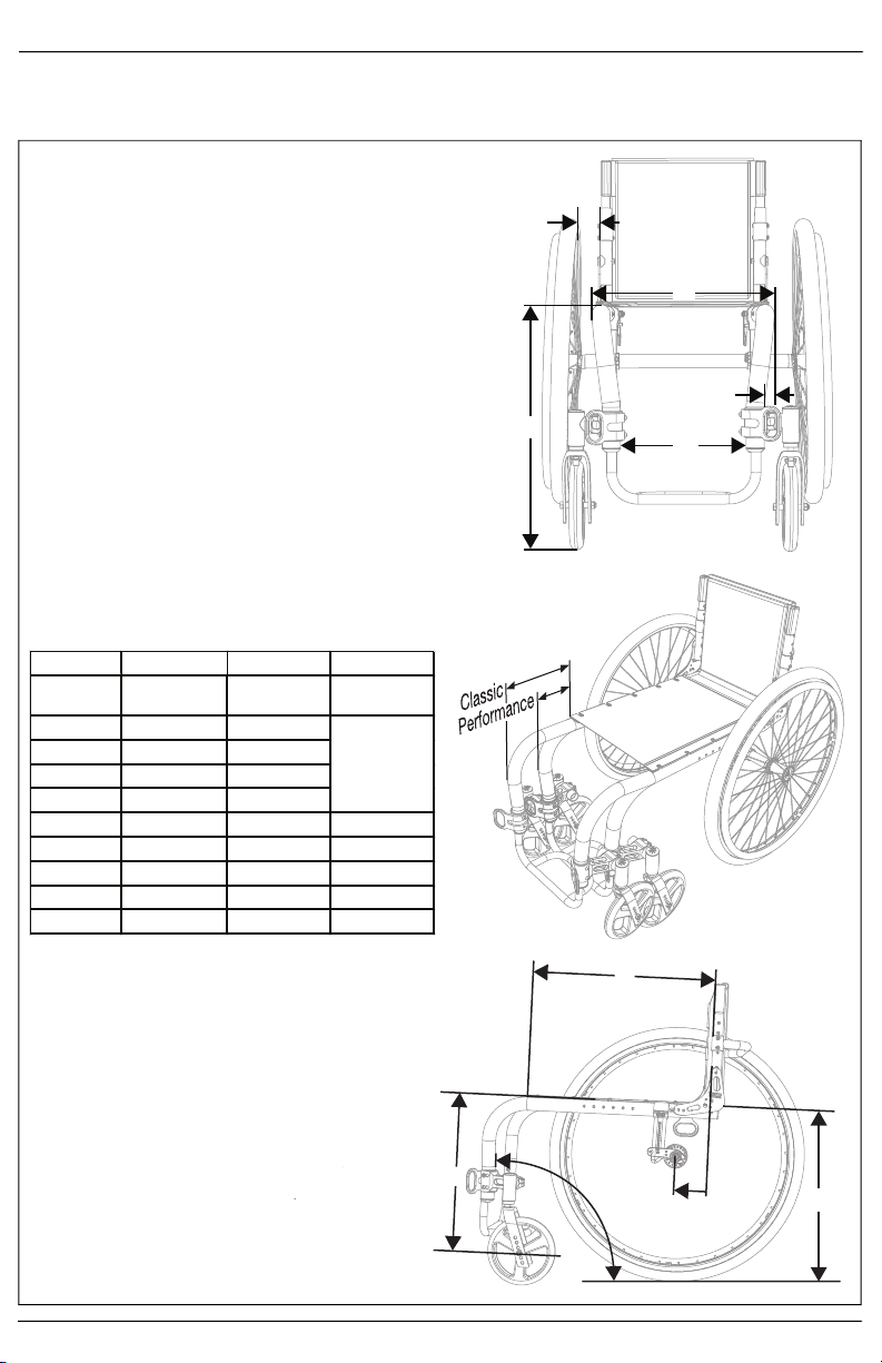
Chair Measurement References
The Tsunami and Little Wave wheelchairs are capable of many adjustments to configure the chair to the
user’s needs. See the diagram below for terms that are commonly used during the process of adjusting the
chairs.
K
F
G
E
A
B
H
D
JI
A. Seat Width (see diagram 1)
Measured from outside of frame tube on one side to the
outside of frame tube on the other side.
B. Seat Depth (see diagram 3)
Measured from front of back posts to front edge of seat sling.
Seat sling starts at beginning of bend at front of frame.
C. Sling Position (see diagram 2)
In Performance Position (0”), sling is at front of frame to keep
chair shorter and more maneuverable. The 1” or 2” seat sling
position extends the frame in front of the sling by that amount.
Adding more frame can improve stability and provide support
to aid in transfers.
D. Front Frame Bend (see diagram 3)
Angle between front seat tube and ground.
E. Footrest Taper (see diagram 1)
Indicates bend of front frame creating footrest. Taper is
measured from outside of seat frame to outside of front tube.
F. Front Seat Height (see diagram 1)
Measured from floor to top of seat tube at front of seat sling.
G. Footrest Width (see diagram 1)
Measured from inside of front tube to inside of front tube on
other side. Footrest width is listed below for each seat width
and taper.
Seat Width Straight 1" Taper 2" Taper
Outside
Measurement
2" Narrower
than Seat Width
4" Narrower
than Seat Width
6" Narrower
than Seat Width
12" 9.5" 7.5"
13" 10.5" 8.5"
14" 11.5" 9.5"
15" 12.5" 10.5"
16" 13.5" 11.5" 9.5"
17" 14.5" 12.5" 10.5"
18" 15.5" 13.5" 11.5"
19" 16.5" 14.5" 12.5"
20" 17.5" 15.5" 13.5"
H. Seat to Footrest Length (see diagram 3)
Measured from front edge of seat sling to top rear of
footrest. Footrest length of at least 2.5” shorter than
front seat height recommended.
I. Rear Seat Height (see diagram 3)
Measured from floor to top of seat tube at front of
back post. Rear seat height is custom to needs.
J. Center of Gravity Preset (see diagram 3)
Measured from front of back post to center of rear
axle. 0” indicates axle will be directly under back post.
K. Rear Wheel Spacing (see diagram 1)
Measured from outside of seat back to inside of rear
tire. Adjustable out .5” from setting.
Diagram 1
Diagram 2
Diagram 3
5
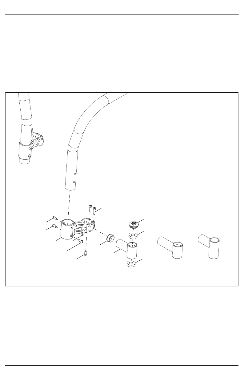
Caster Mount
NOTE: The footrest tube must be removed prior to installation to allow the caster mount to slide
onto the chair frame.
1. Install the two end caps (G & I) and two bearings (J) into the caster housing (H).
2. Install the caster housing assembly into the caster mount (B) and secure with three bolts (E & F) using a
4mm Allen wrench.
3. Install the caster mount assembly onto the chair frame and secure by installing the four bolts (A, C & D)
through the caster mount and chair frame holes using a 4mm and a 5mm Allen wrench.
NOTE: There are three different sizes of the caster housing available - standard, extended and tall.
Caster housing size is dependent on caster size, front seat height and footplate selection. If
additional help is needed regarding caster housing size please contact Ki Mobility customer
service.
Standard
(3.2” L x 1.9” H)
Extended
(3.9” L x 1.9” H)
Tall
(3.2” L x 2.6” H)
Assembled
A
A
BC
D
E
F
G
H
I
J
J
6
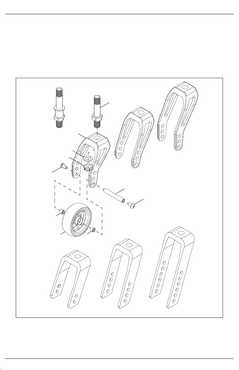
Caster Forks and Stems
NOTE: Different configurations achieve the desired front seat height based on caster size. If making
a change to front seat height or caster size, the combination of fork and stems could vary.
1. Install stem (A) into fork (B) with washer (C) and nut (D) using a 16mm wrench.
2. Install caster wheel (H) into fork (D) with two screws (E), a threaded barrel (F) and two spacers (G) using
two 4mm Allen wrenches.
NOTE: There are two sizes of caster stems (standard and +3/4") and three sizes of slotted forks
(short, standard and tall) and standard forks (4", 5" and 6") that can be used. The image below
shows the stems and forks. The installation process is the same for whichever stem and fork you
use.
Std Fork 4” Std Fork 5” Std Fork 6”
Slotted
Fork -
Short
Slotted
Fork -
Medium
Slotted
Fork - Tall
Std Stem+3/4” Stem
A
B
D
C
E
E
F
G
G
H
7
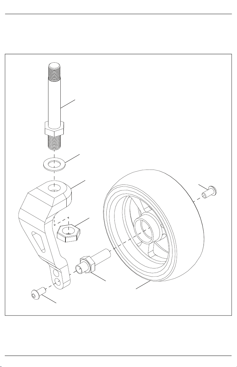
Caster Forks and Stems
Single Sided Fork
1. Install stem (A) into single sided fork (C) with washer (B) and nut (D) using a ½" wrench.
2. Install caster wheel (G) onto fork (C) with two screws (E) and the axle shaft (F).
NOTE: There are three sizes of caster stems (standard, +3/4" and +1") that can be used. The
installation process is the same for whichever stem and fork you use.
A
B
C
D
E
F
E
G
8
Caster Forks and Stems
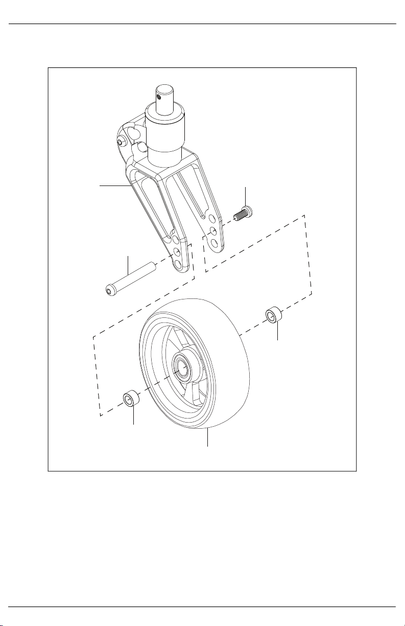
Frog Legs Ultra Sport Fork Assembly
1. Install Frog Leg Ultra Sport Fork (A) onto caster wheel (E) with axle (B), screw (C) and two spacers (D)
using two 4mm Allen wrenches.
A
B
C
D
D
E
9
Caster Forks and Stems
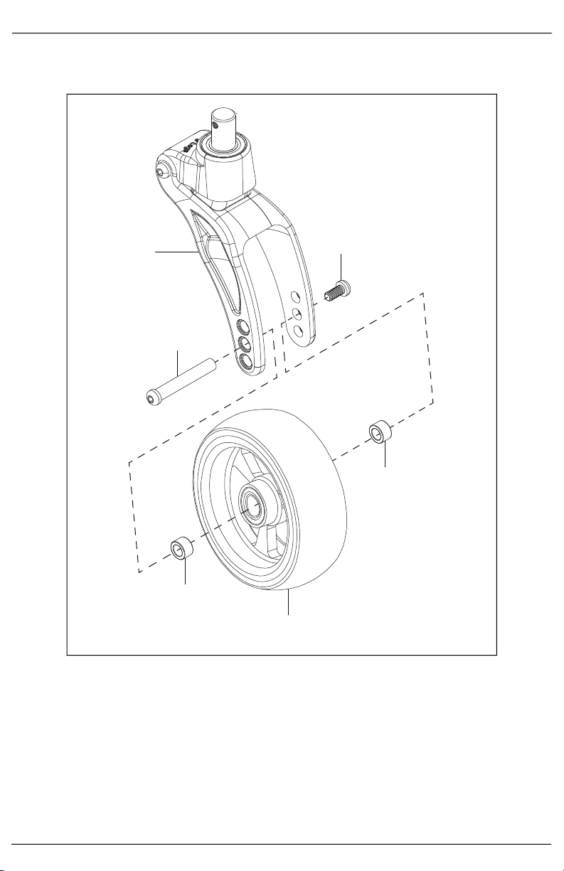
Frog Legs Phase 2 Carbon Fork Assembly
1. Install Frog Leg Phase 2 Carbon Fork (A) onto caster wheel (E) with axle (B), screw (C) and two spacers
(D) using two 4mm Allen wrenches.
A
B
C
D
D
E
Questo manuale è adatto per i seguenti modelli
1
Indice
Altri manuali Ki Mobility Ausilio alla mobilità

Ki Mobility
Ki Mobility Little Wave Tyke Manuale di installazione e funzionamento

Ki Mobility
Ki Mobility Little Wave FLIP Manuale utente

Ki Mobility
Ki Mobility Tyke Manuale utente

Ki Mobility
Ki Mobility Focus CR Manuale di installazione e funzionamento

Ki Mobility
Ki Mobility Axiom Back PB Manuale di installazione e funzionamento

Ki Mobility
Ki Mobility Little Wave "Flip" XP Manuale di installazione e funzionamento


