King Controls 9702 Manuale utente
Automatic Satellite System
9702 9702-LP
Installation and Operating Instructions
11200 Hampshire Avenue South, Bloomington, MN 55438-2453
Phone: (800) 982-9920 Fax: (952) 922-8424
www.kingcontrols.com
1347 REV M
Satellite Solutions for Mobile Markets
®

Page 1
IMPORTANT!
The satellite TV market is expanding and changing. The information in this manual was
accurate at the time of printing. If your King-Dome does not operate as outlined in this
manual please call King Controls at (800) 982-9920 or visit our website at
www.kingcontrols.com.
TABLE OF CONTENTS
Section Contents Page
1. INTRODUCTION.....................................................................................2
2. DEFINITION OF TERMS........................................................................3
3. INSTALLATION..................................................................................4-11
4. OPERATION .........................................................................................12
5. MULTI-SWITCH ....................................................................................13
6. TROUBLESHOOTING..........................................................................14
7. MAINTENANCE....................................................................................15
8. LIMITED WARRANTY ..........................................................................16
DIRECTV®is an official trademark of DIRECTV, division of GM Hughes Electronics Corporation.
Dish Network®is an official trademark of Echostar Communications Corporation.
Bell ExpressVu®is an official trademark of Bell Canada.
DVB®is a trademark of the DVB Digital Video Broadcast Project (1991-1996)
Page 2
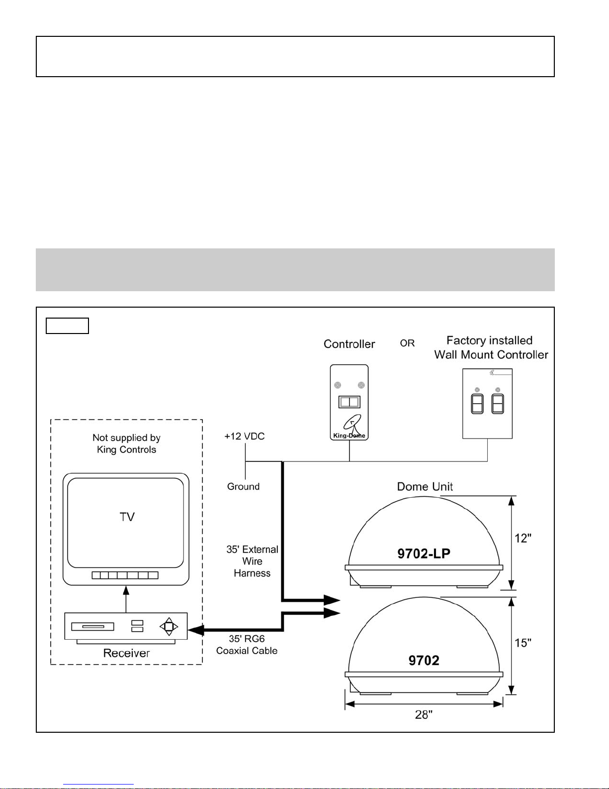
The King-Dome Automatic Satellite System includes 2 main components (Fig. 1).
Dome (Antenna) Unit Located on the roof of the vehicle. The dish is covered by a
protective dome that keeps operational components free from
the elements.
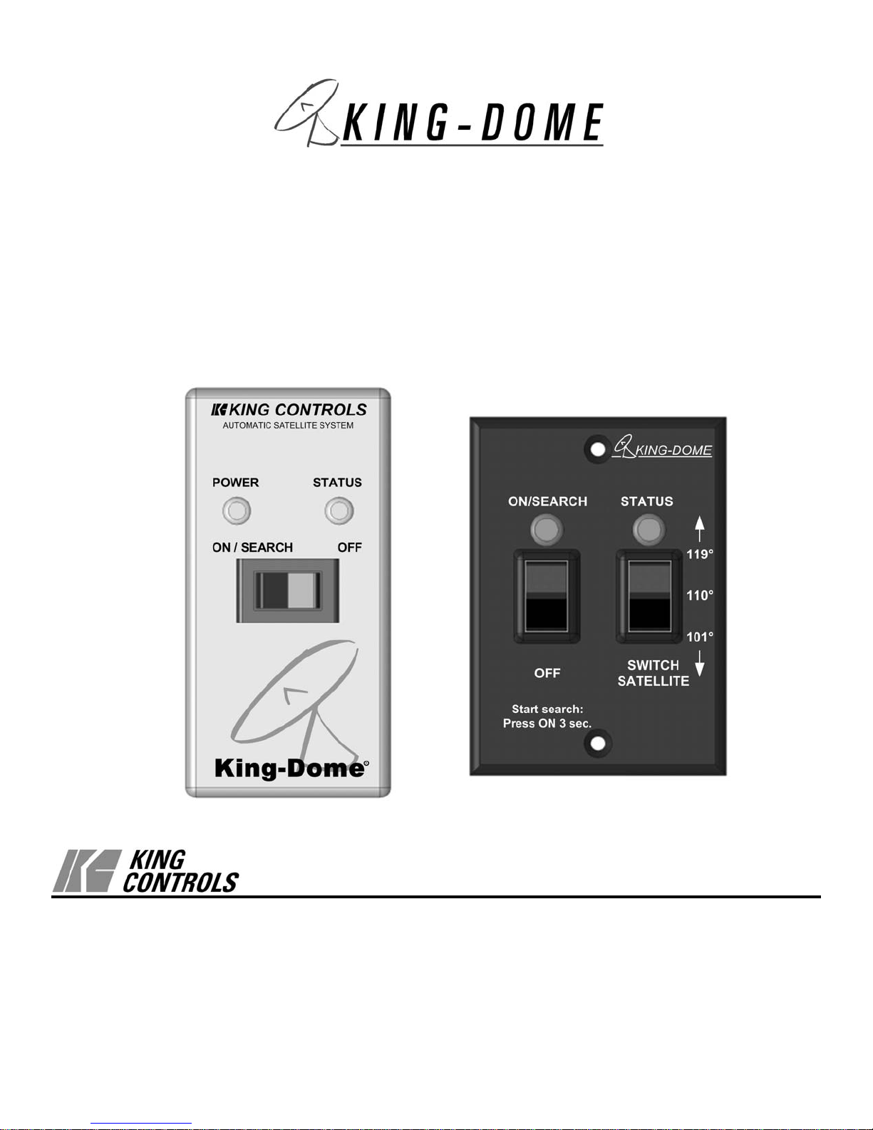
Controller Located in the vehicle. Activates the search mode and
provides limited diagnostic functions using the status light.
SECTION 1 INTRODUCTION
Note: A TV, satellite receiver, and program subscription are also required for satellite TV
viewing. (Not supplied by King Controls.)
Fig. 1
KING CONTROLS
POWER STATUS
ON / SEARCH OFF
ON/SEARCH
OFF SWITCH
SATELLITE
STATUS
KING-DOME
Page 3
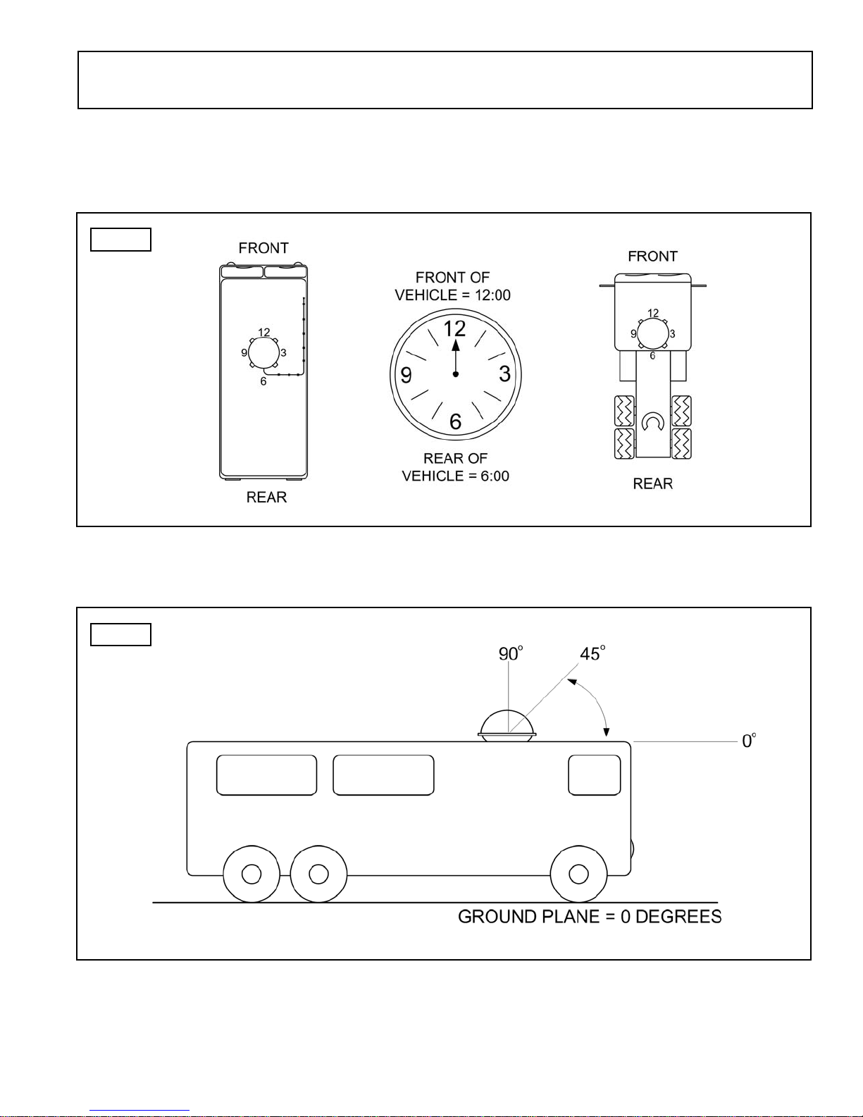
AZIMUTH: Circular rotation around the vehicle.
(like a clock face: front of vehicle is 12:00, rear is 6:00) (Fig. 2)
ELEVATION: Angle in degrees measured from the ground plane (Fig. 3).
SIGNAL STRENGTH: Intensity of electronic signal received from the satellite transmission.
SECTION 2 DEFINITION OF TERMS
Fig. 2
Fig. 3
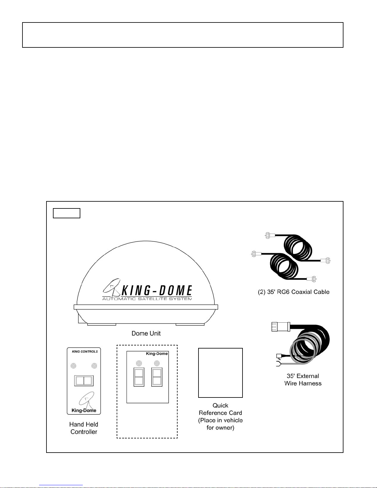
KIT CONTENTS:
1. Unpack and identify all components (Fig. 4).
Page 4
SECTION 3 INSTALLATION
Fig. 4
TOOLS AND MATERIALS REQUIRED:
- drill and drill bit set
- tape measure
- 7/16” open end wrench (coax connections)
- adhesive sealant (compatible with roof material)
- appropriate fasteners to install all components and wiring
- 5/32” allen wrench, channel lock or pliers (to remove shipping bolt)
- wire cutter (to remove shipping tie strap)
POWER STATUS
ON / SEARCH OFF
Optional
Wall Mount
Controller
King Dome Operating Instructions
1. Turn tv and satellite receiver on.
The tv screen should display “searching for
satellite signal” or “Acquiring satellite signal.
IMPORTANT Do not use the tv or receiver
controls until you have found a satellite.
2. Press and hold the king dome switch to
on/search for a full 4 seconds.
3. wait for status light to turn stead green.
4. turn to a satellite channel that you normally
watch. Is there a picture?
questions? refer to owner’s manual
KING-DOME
KIT CONTENTS
SWITCH
SATELLITE
STATUS
ON/SEARCH
OFF
Page 5
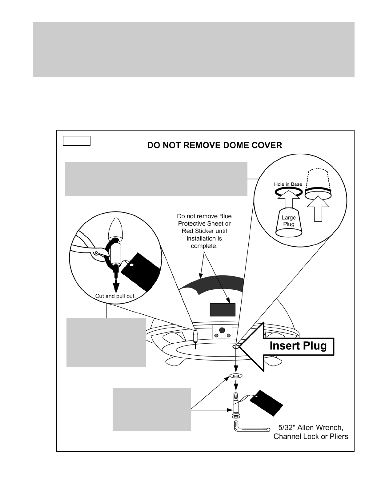
IMPORTANT! The tie strap and spacer, and the bolt and washer must be removed from
the bottom of the dome unit prior to installation. DO NOT REMOVE THE
DOME COVER TO REMOVE THESE SHIPPING RESTRAINTS.
YOU MUST PLUG THE SHIPPING BOLT HOLE WITH THE SUPPLIED PLUG.
2. Remove and discard the tie strap and spacer, and the bolt and washer that pass through
the bottom of the base (Fig. 5).
3. Insert provided plug into hole that was occupied by the shipping bolt (Fig. 5).
Fig. 5
IMPORTANT!
Remove and discard
Tie Strap and Plastic
Spacer prior to
installation.
IMPORTANT!
Remove and discard
Bolt and Washer
prior to installation.
IMPORTANT!
After removing shipping bolt, firmly insert plug
into hole. Plug should be almost flush with base.

Page 6
DOME LOCATION
4. Select an area on the roof for the dome unit and the location where the wiring will enter
the vehicle through the roof to the satellite receiver, controller, and 12 volt power source
inside, using the following criteria:
a) The shortest distance between the dome unit and the satellite receiver is most
desirable.
b) The dome unit requires a 28 inch diameter mounting area.
c) The dome unit should be mounted on the centerline of the vehicle.
d) There must be no “line of sight” obstructions. Air conditioning units, other antennas,
and storage areas that are too close to the dome unit may prevent the satellite
signal from reaching the dish (Fig. 6).
HEIGHT OF
OBSTRUCTION
APPROXIMATE
MINIMUM DISTANCE
TO DOME EDGE
10” 8”
11” 10”
12” 12”
13” 14”
14” 16”
15” 18”
16” 20”
Fig.6
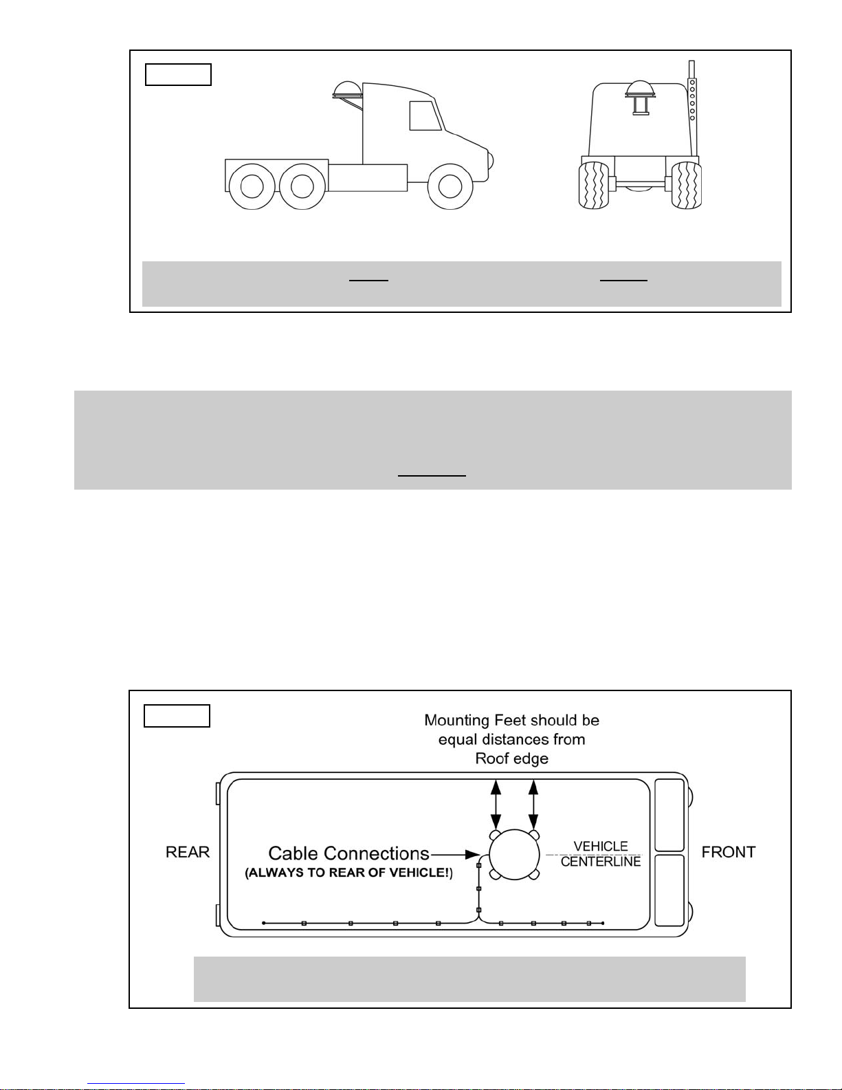
IMPORTANT! For installations on trucks with air shields, a bracket must be used for
mounting the dome unit. The dome unit MUST be mounted to the air ride
cab: NEVER to any structure mounted directly to the frame.
See bracket instructions for proper installation (Fig. 7).
Page 7
5. Place dome unit on installation location chosen using the criteria discussed in the
previous section. Shipping restraints must be removed (Fig. 5, Page 5), and cable
connections must be positioned facing rear of vehicle.
6. The dome unit must be positioned so that both feet on each side of the vehicle are equal
distances from the roof edge. This should be checked by measuring the distance from
each feet to the roof edge. Confirm that these measurements are equal (Fig. 8).
IMPORTANT! Make sure shipping restraints are removed from bottom of dome unit
(Fig. 5, Page 5).
Cable connections must ALWAYS be positioned facing the rear of vehicle.
Example of truck installation using bracket.
See bracket instructions for proper installation.
Fig. 8
Fig. 7
IMPORTANT! The dome unit MUST be mounted to the air ride cab: NEVER to any structure
mounted directly to the frame.
DOME INSTALLATION
IMPORTANT! The dome should never be mounted so that it is tilted more than
two degrees in any direction.
Page 8
7. Mount the dome unit. Use the pre-drilled holes in the mounting feet as a guide to install
the fasteners into the roof. Use additional fasteners whenever necessary.
8. Test that the dome unit is secure by pulling upward from each foot location.
EXTERNAL WIRING
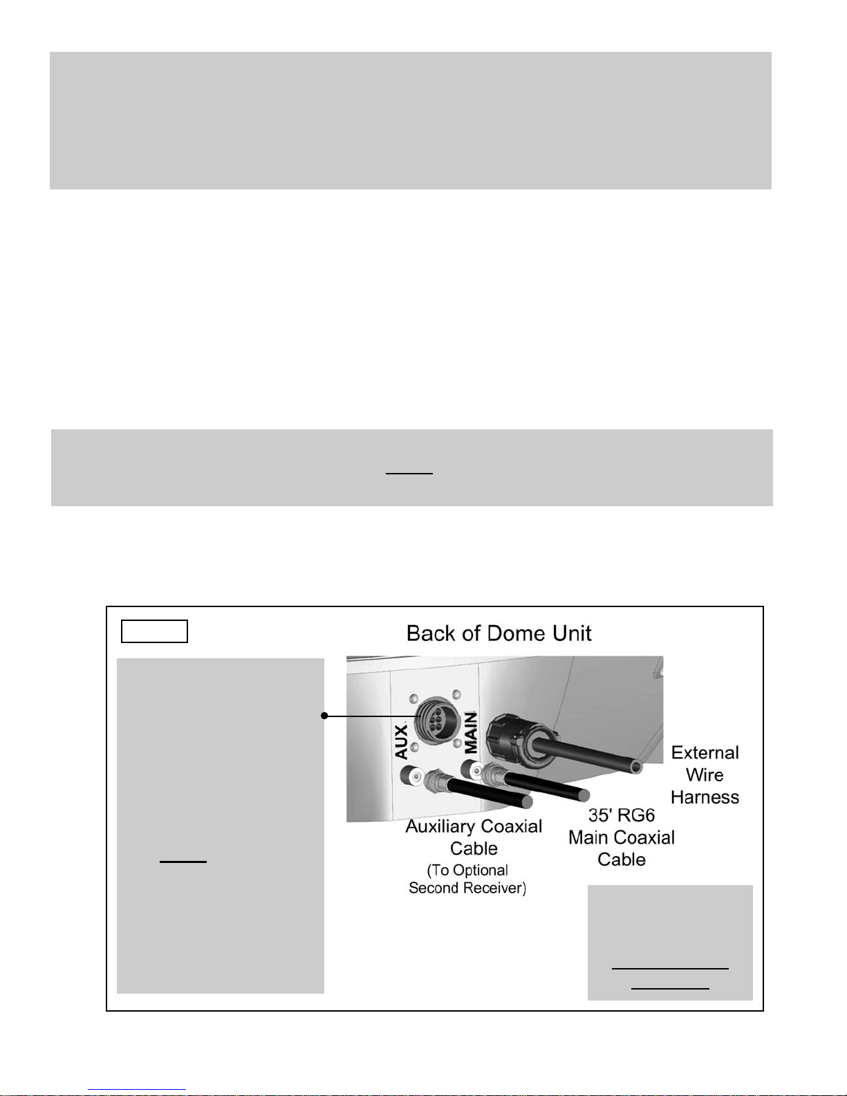
9. Plug external wire harness into wiring port on back of dome unit and tighten connection
until it clicks past the detent lock (Fig. 9).
10. Connect 35’ coax cable to coax port labeled MAIN on back of dome unit and tighten
connection. If using a second receiver, connect second 35’ coax cable to coax port
labeled AUX and tighten connection. Do not over tighten coax connections (Fig. 9).
Note: The installer is responsible for determining the most appropriate fastener to secure the
dome to the roof. Depending on the roof material, fasteners such as lag screws, well
nuts, sheet metal screws, toggle bolts and T anchors may be used, and should always
be used in combination with a roof compatible sealant.
IMPORTANT! The installer is responsible for weatherproofing all holes with sealant.
Note: The King-Dome is wired for a dual LNB. There are two coaxial ports on the back of the
dome unit. The one labeled “MAIN” MUST be connected to the main receiver in vehicle.
The one labeled “AUX” can be used for an additional receiver.
Fig. 9
IMPORTANT!
Coax connections
should be snug.
DO NOT OVER
TIGHTEN!
IMPORTANT!
The alignment tabs on
the wiring port and the
external wire harness
plug must match up
when engaging plug
onto port.
YOU MUST TIGHTEN THE
PLUG UNTIL IT CLICKS
PAST THE DETENT
LOCK.
(A channel lock pliers
may be used to tighten
the connection.)
Page 9
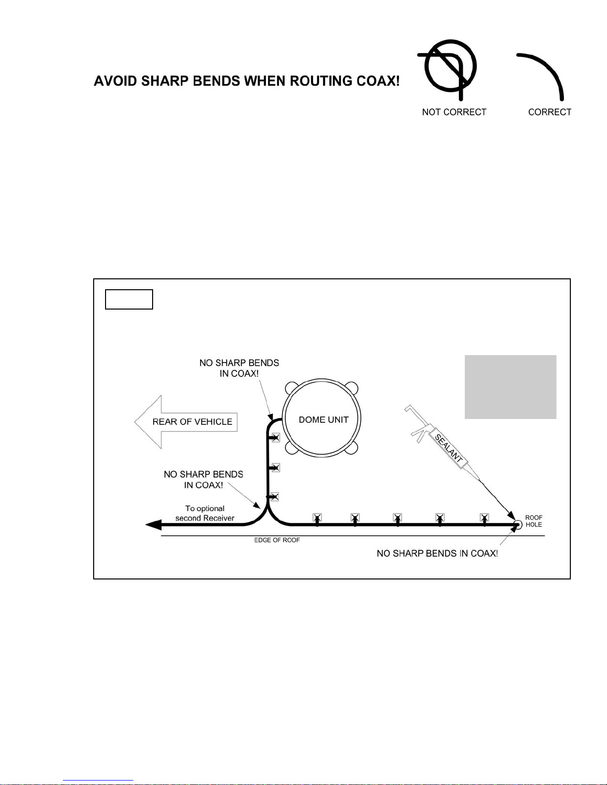
11. Run wires from the back of the dome unit to the roof edge, then along edge to location
where wiring will be fed into the vehicle. (If installing an optional second receiver, run
auxiliary coax to location where it will enter the vehicle.) Secure wiring to roof every 12-
18 inches (Fig. 10).
12. Drill 5/8” hole through the roof and into the cabinet where receiver is stored. Feed wiring
down through hole. Seal opening with roof compatible sealant so that it is entirely
waterproof (inside and outside of the 5/8” hole). Repeat for optional second receiver
(Fig. 10).
Fig. 10 TYPICAL ROOF INSTALLATION - OVERHEAD VIEW
IMPORTANT!
Sealant must
be roof
compatible.
13. Remove blue protective sheet and red “position to rear” sticker from the dome unit.
Questo manuale è adatto per i seguenti modelli
1
Indice
Altri manuali King Controls Sistema TV satellitare


