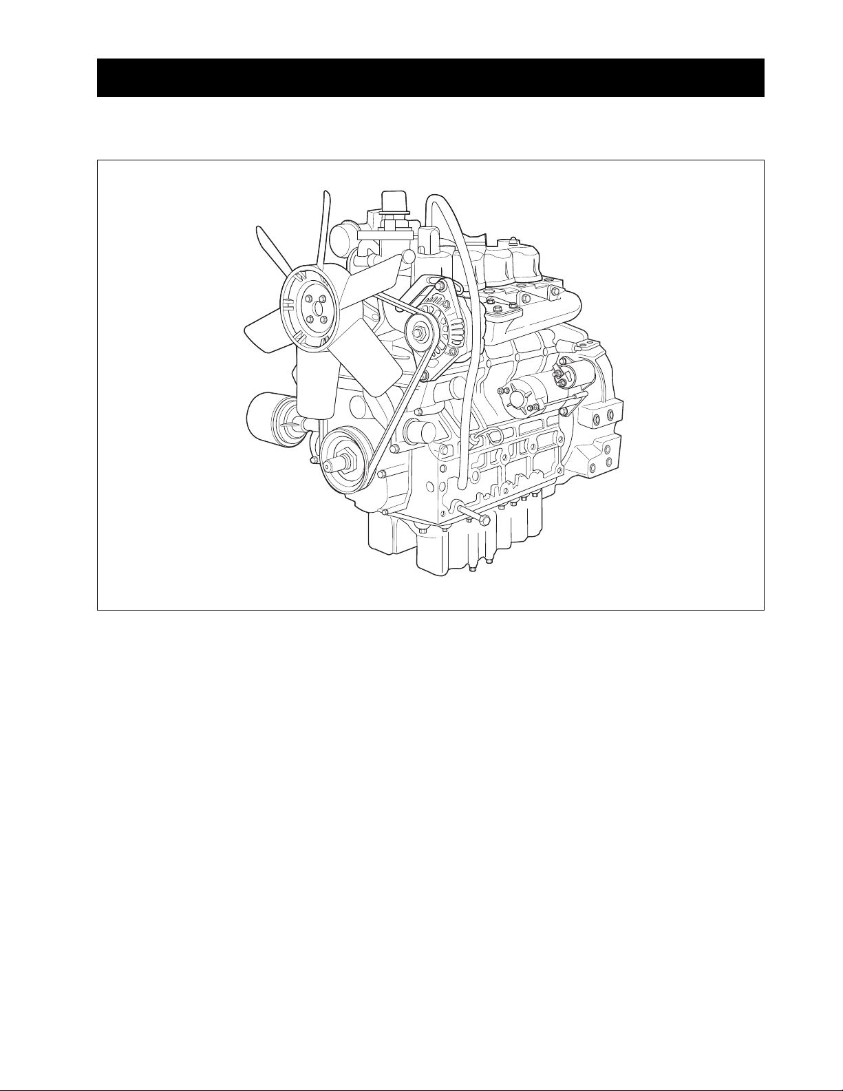
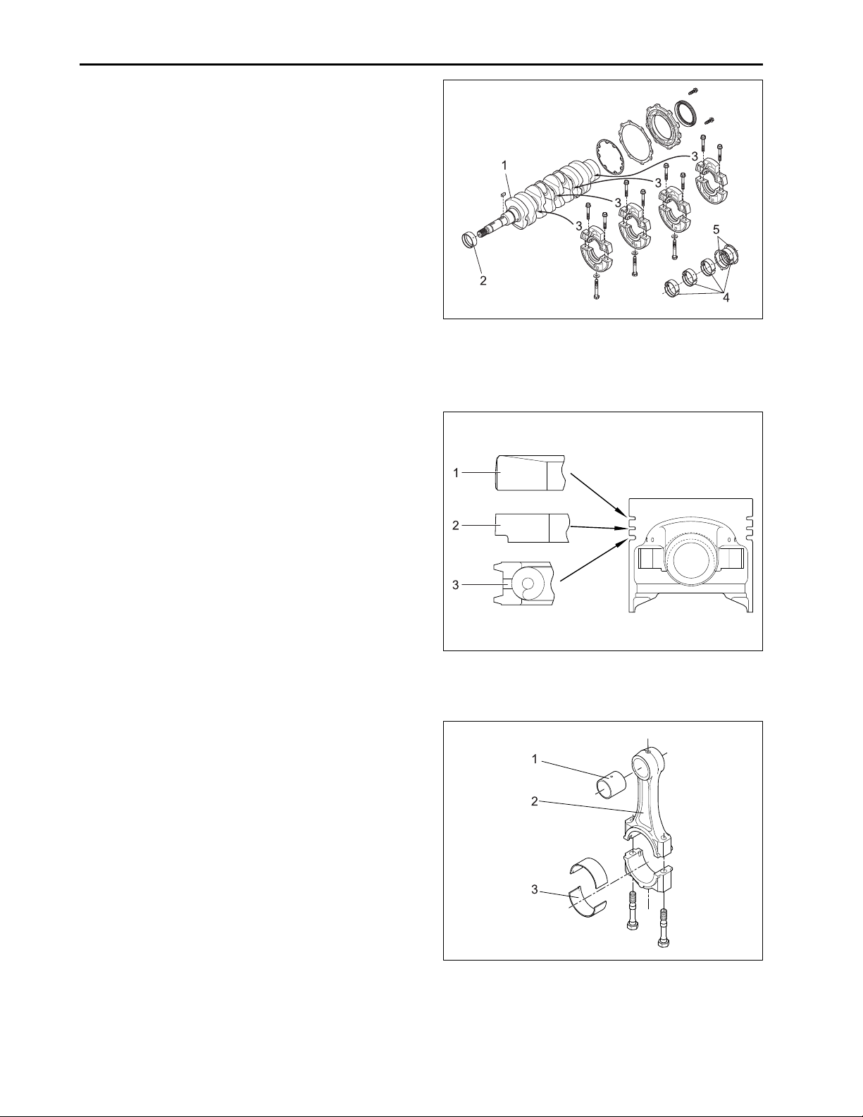
Kioti 4A200T Manuale di istruzioni

CHAPTER 2
ENGINE


ENGINE
2-3
1. GENERAL
1.1 APPEARANCE
632W201A
The DAEDONG A series engines are vertical, water-
cooled, 4-cycle, three or four cylinders diesel engines,
they concentrate DAEDONG’s foremost technologies.
With swirl combustion chamber, bosch K type fuel in-
jection pump, well-balanced designs, they feature
greater power, low fuel consumption, less vibration and
noise, and low emission.

ENGINE
2-4
1.2 SPECIFICATIONS
* NOTE: Change of parts are not subject to advance notice.
MODEL
Type
Number of cylinder
Bore and stroke mm (in.)
Total displacement (in3.)
Combustion chamber
POWER (NET) PS/rpm (kW. rpm)
Maximum idling speed rpm
Minimum idling speed rpm
Order of firing
Direction of rotation
Injection pump
Injection pressure
Injection timing (Before T.D.C)
Compression ratio
Fuel
Lubricant
Dimensions mm
(length x width x height) (in.)
Dry weight kg (kg, lbs.)
4A220
Vertical, water-cooled,
4-cycle diesel engine
4
87.0 x 92.4 (3.43 x 3.64)
2.197 (134.1)
vortex chamber
43/2,700 (30.9/2,700)
2,900
850 ~ 900
1-3-4-2
Counterclockwise
(viewed from flywheel side)
Bosch K TYPE mini pump
140 ~ 150 kgf/cm2
(13.73 ~ 14.71 MPa, 1991 ~ 2133 psi)
18°
22 : 1
Diesel fuel
Engine oil SAE 15W-40
817.3 x 488.1 x 735.8
(32.2 x 19.2 x 29.0)
207 (456)
4A200T
Vertical, water-cooled,
4-cycle diesel engine (Turbo)
4
83.0 x 92.4 (3.27 x 3.64)
1.999 (122.0)
vortex chamber
47/2,600 (34.6/2,600)
2,800
850 ~ 900
1-3-4-2
Counterclockwise
(viewed from flywheel side)
Bosch K TYPE mini pump
140 ~ 150 kgf/cm2
(13.73 ~ 14.71 MPa, 1991 ~ 2134 psi)
12°
22 : 1
Diesel fuel
Engine oil SAE 15W-40
817.3 x 542.0 x 735.8
(32.2 x 19.2 x 29.0)
211 (465)

ENGINE
2-5
632W204A 632W203A
1.3 PERFORMANCE CURVE

ENGINE
2-6
632W205A
1.4 DIMENSIONS
4A220
4A200T
4A220
4A200T
Sample/td Spec.
A
697.3 (27.45)
697.3 (27.45)
G
736 (28.98)
736 (28.98)
B
817.3 (32.18)
817.3 (32.18)
H
260 (10.24)
260 (10.24)
C
280 (11.02)
280 (11.02)
I
240 (9.45)
240 (9.45)
D
φ
400 (15.75)
φ
400 (15.75)
J
φ
321 (12.64)
φ
321 (12.64)
E
502.6 (19.79)
519 (20.43)
K
104.5 (4.11)
104 (4.09)
F
262.5 (10.33)
282.4 (11.12)
L
-
542 (21.34)
mm (in.)
1.5 GENERAL WARNING
• When disassembling, arrange each part on a clean
place. Do not mix them up. Replace bolts and nuts
where they were.
• When connecting instruments to electrical
equipment, first disconnect battery negative
terminal.
• Replace gaskets or O-rings with new ones when
reassembling, and apply grease on a O-rings and
the oil seals when reassembling.
• When exchanging parts, use genuine DAEDONG
parts to maintain engine performance and safety.
• To prevent oil and water leakage, apply non-drying
adhesive to the gaskets according to this manual
before reassembling.
• When hoisting up the engine, use the hook pro-
vided on the cylinder head.
• When installing the engine, use the hook provided
on the cylinder head.
• When installing external cir-clips or internal cir-clips,
direct corner end to the non- loosening direction.

ENGINE
2-7
632W208A
632W207A
632W206A
2. STRUCTUREAND FUNCTION
2.1 BODY
A. CYLINDER HEAD
The cylinder head is made of special alloy cast iron
which can resist high temperature and pressure
caused by combustion. The intake and exhaust ports
are arranged cross-flow type to get high combustion
efficiency by protecting the suction air from being heated
and expanded by heated exhaust air.
The Daedong vortex type combustion chamber is de-
signed for high efficiency combustion and reducing fuel
consumption. The glow plugs assures easy engine
starts even at (-) 15 °C (5 °F).
B. CYLINDER BLOCK
The engine has a high durability tunnel-type cylinder
block. Furthermore, liner less type, allows effective cool-
ing, less distortion, and greater wear-resistance using
special material. The noise is reduced to a minimum
because each cylinder had its chamber.
(1) Combustion Chamber
(2) Inlet Port
(3) Exhaust Port
(4) Injection Nozzle
(5) Glow Plug
(6) Cylinder Head

ENGINE
2-8
632W211A
632W210A
632W209A
(1) Top Ring (3) Oil Ring
(2) Second Ring
(1) Small End Bushing (3) Crankpin Bearing
(2) Connecting Rod
E. CONNECTING ROD
The connecting rod (2), which converts the reciprocat-
ing motion of the pistons caused by the fuel combus-
tion into the rotating motion of the crankshaft, is made
of harden forged steel. The connecting rod has bear-
ings at both ends. The small end has a solid type bear-
ing (small end bushing (2)) and the big end has a split
type bearing (crankpin bearing (3)).
D. PISTONAND PISTON RINGS
The piston are made of an aluminum alloy which is
temperature and pressure resistant. Three rings in-
stalled in grooves of the piston. The top ring (1) is a
keystone type, which can withstand heavy loads, and
the barrel face on the ring fits well to the cylinder wall.
The second ring (2) is an undercut type, which pre-
vents the oil from being carried up. The oil ring (3) has
chambered contact faces and an expander ring, which
increase the pressure of the oil ring against the cylin-
der wall to scrape the oil. The top ring is plated with
hard chrome to increase wear resistance (The ring of
4A200T engine is mode of a special steel).
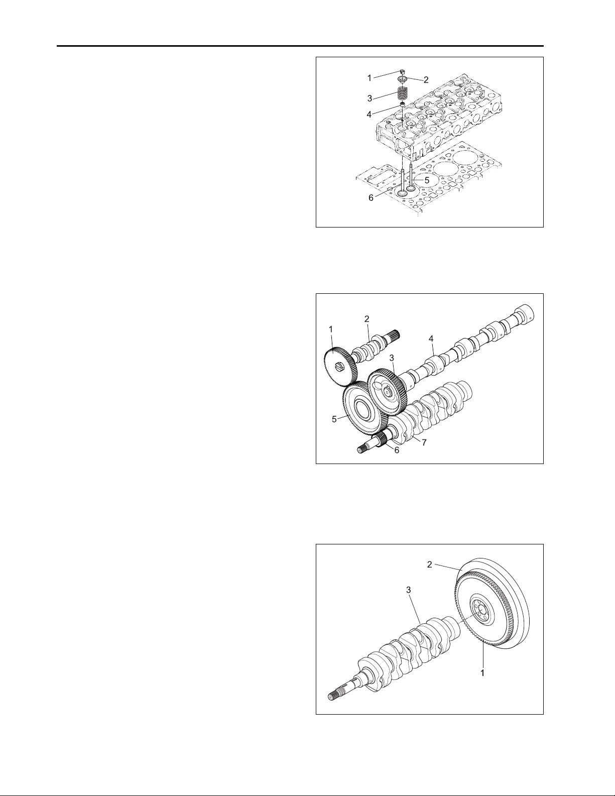
C. CRANKSHAFT
The crankshaft is made of forged steel and the journals,
the crankpins and the bearing surface for the oil seal
are induction-hardened to increase wear resistance.
Each crankshaft journal is supported by the main bear-
ing case (3) having a bearing inside.
The front crankshaft bearing (2) is a solid type bushing
and rear and intermediate bearings are a split type.
The crankshaft’s bearings have oil holes for lubricant
flow.
(1) Crankshaft (4) Crankshaft Bearing 2
(2) Crankshaft Bearing (5) Thrust Bearing
(3) Main Bearing Case

ENGINE
2-9
632W214A
632W213A
632W212A
(1) Rocker Arm (4) Rocker Arm Bracket
(2) Lock Nut (5) Rocker Arm Shaft
(3) Adjusting Screw
F. CAMSHAFT
The camshaft (3) is made of forged steel and it’s jour-
nals and cams are hardened to increase wear
resistance. The cams on the camshaft open and close
the intake and exhaust valves with the push rods and
rocker arms. The journals and their bearings are force-
lubricated.
(1) Cam Gear (3) Camshaft
(2) Camshaft Stopper
(1) Fuel Camshaft (2) Injection Pump Gear
G. FUEL CAMSHAFT
This fuel camshaft is made of forged steel and its cams
are hardened and tempered to increase wear
resistance. The cams on the fuel camshaft (1) drive
the injection pump and the fuel transfer pump. The
governor balls are installed on the fuel camshaft to
control the engine speed.
H. ROCKER ARMASSEMBLY
The rocker arm assembly includes the rocker arms (1)
and an adjusting screw (3), which is at the end of rocker
arm and rests on the push rod, rocker arm brackets (4)
and rocker arm shaft (5). The rocker arms are activated
by the reciprocating motion of the push rods and open
or close the intake and exhaust valves. The rocker arm
and other parts are lubricated through the drilled holes
of the brackets and the rocker arm shaft.

ENGINE
2-10
632W217A
632W216A
632W215A
(1) Valve Spring Collet (4) Valve Stem Seal
(2) Valve Spring Retainer (5) Exhaust Valve
(3) Valve Spring (6) Intake Valve
(1) Injection Pump Gear (5) Idle Gear
(2) Fuel Camshaft (6) Crankshaft Gear
(3) Camshaft Gear (7) Crankshaft
(4) Camshaft
(1) Ring Gear (3) Crankshaft
(2) Flywheel
K. FLYWHEEL
The flywheel is installed on the rear end of the
crankshaft. Its inertia keeps the engine turning at a
constant speed, while the crankshaft tends to speed
up during the power stroke and to slow down during
other stokes. The flywheel has a ring gear (1), which
meshes with the drive pinion of the starter.
The flywheel has marks “TC” and “FI” on its outer rim.
The mark TC shows the piston’s top dead center and
the mark FI shows the fuel injection timing, when they
are aligned with the mark of window on the clutch hous-
ing.
I. INTAKE AND EXHAUST VALVES
The valve and its guide of the intake are different from
those for the exhaust. Other parts, such as the spring,
spring retainers, valve spring collets, valve stem seals
are the same for both the intake and the exhaust. All
contact or sliding surfaces are hardened to increase
wear resistance.
J. TIMING GEARS
The crankshaft drives the oil pump and the idle gear
engaged fuel camshaft and camshaft. The timing for
opening and closing the valves is extremely important
to achieve effective air intake and sufficient gas exhaust.
The appropriate timing can be obtained by aligning the
mark on the crankshaft gear (6) with one the idle gear
(5), idle gear with camshaft gear, idle gear with injec-
tion pump gear, when assembling.
Questo manuale è adatto per i seguenti modelli
1
Indice


