KOB Pyromat DYN 45 Manuale del sistema

Spec Sheet
Burner System Loader System
PYROMAT-DYN
1
Köb Holzheizsysteme GmbH, Flotzbachstr. 33, A-6922 Wolfurt, Tel. +43/5574/6770-0, Fax 65707, E-Mail: [email protected]
Subject to technical changes
3010-1
2009-03-01_GB
Description:
The PYROMAT-DYN is a boiler with patented double combustion chamber. Which means that the burner system enables
optimized operation with automatic loading (shavings, chippings from waste wood, wood chippings, max. W35; G50) and
may also be used with logs. A large loading shaft with loading lid and separate grid has been fitted in front of the main
combustion chamber to make loading wood easy. In automatic operation, the burner system is suitable for all dry to moist
wood fuels (max. W35). The control is integrated into the burner system with connector-ready cabling to the sensors and
motors. Which permits simple and rapid installation. The PYROMAT-DYN has been tested and approved in accordance
with the latest quality criteria in compliance with EN 303-5 heating boilers for solid fuels,
CE certification as per European Machinery Directive and continuous quality assurance by TÜV.
Max. flow temperature: 100°C
Max. operating pressure: 3.0 bar
Electric connection: 3 x 400V
Safety heat exchanger: Built into the boiler
Function:
- In manual operation, chopped wood and waste wood are degassed on the incineration grate situated before the
main combustion chamber. Simultaneous operation with automatic loading is not possible.
- In automatic operation the feed auger conveys the material to be burned into the main combustion chamber for
degasification.
The fasteners for the burn-back sensor and the thermally operated extinguisher valve are situated on the conveyor
pipe. Above the auger, there is a metering container with a light barrier to ascertain the level of the fuel isolating layer
required according to TRD 414.
- In automatic operation the material to be incinerated is ignited automatically by an electric hot air blower.
The combustion gases are entirely burned out in the afterburn chamber together with secondary airflow.
- The ash is mechanically removed from the main combustion chamber.
- In the upright pipe heat exchanger, the thermal energy from the combustion gases is transferred to
the boiler water. The vertical surfaces of the heat exchanger are regularly cleaned by motor-driven,
moving coil springs.
- The speed-controlled exhaust blower was specially designed for operation in wood heating systems and is very quiet.
- The negative pressure created by it produces a high degree of safety against burn-back in automatic operation and a
convenient feed function in manual operation.
- An integrated heat management system (accumulator-temperature-guided with return circuit valve) enables the best
possible controlled operation.
Scope of delivery:
-Boiler with double combustion chamber, ash pan, kindling and cleaning utensils, coil springs for the heat exchanger
cleaning system, mechanical drive with position sensor for removing the ash from the main combustion chamber.
- Exhaust blower, plug-and-play
- Integrated ECOTRONIC control system (decentralised microprocessor system via CAN-bus), consisting of:
Boiler control panel, control module for mounting preferably on a wall, bus cable for the drive motors wired to
output plug
- Feed auger with isolating layer, incl. Starttec drive via CAN-bus (including data transmission line) for gentle start-up,
automatic reversing and overload safeguard, light barriers for combustion chamber and metering container
-Automatic ignition system
- Burner group ready-installed on connecting flange, consisting of burner pump, two blockage units
Burner control valve, forward and return flow sensors incl. fittings.
-Three KTY heat accumulator sensors, incl. dipping shell (1/2" x 280 mm long) wired together to plug
-Four-pin master switch, uninstalled (for installation near the control module)
ACCESSORIES for PYROMAT-DYN (Article KPM-…) at extra charge:
Name Article Text Sizes Use
Reduction exhaust connection KPM-… 3110 3110 existing chimney 180 mm dia.
Exhaust blower-intake port 90° KPM-… 3110 3110 special exhaust gas conveyance
Exhaust gas deduster KPM-… 3110 3110 optional
De-ashing into the container 20 L KPM-DYN-AS 3200 3200 optional
ECO function for PYROMAT-DYN LSR-DYN 3200 - for use with logs; incl. storage
Error report 230 V ECO-ZA 3200 - optional
External requirements ECO-ANF 3200 - optional
Discharge systems ADE/ADF 3300 3300 material transport silo to boiler
Heater control, module extensions ECO-… 4000ff - optional
Data cable for operating module ECO-… 4020 - required
Boiler safety devices K-… 4500 - optional
Extinguishing equipment K-… 4550 4550 optional

Spec Sheet
Burner System Loader System
PYROMAT-DYN
1
Köb Holzheizsysteme GmbH, Flotzbachstr. 33, A-6922 Wolfurt, Tel. +43/5574/6770-0, Fax 65707, E-Mail: [email protected]
Subject to technical changes
3010-2
2009-03-01_GB
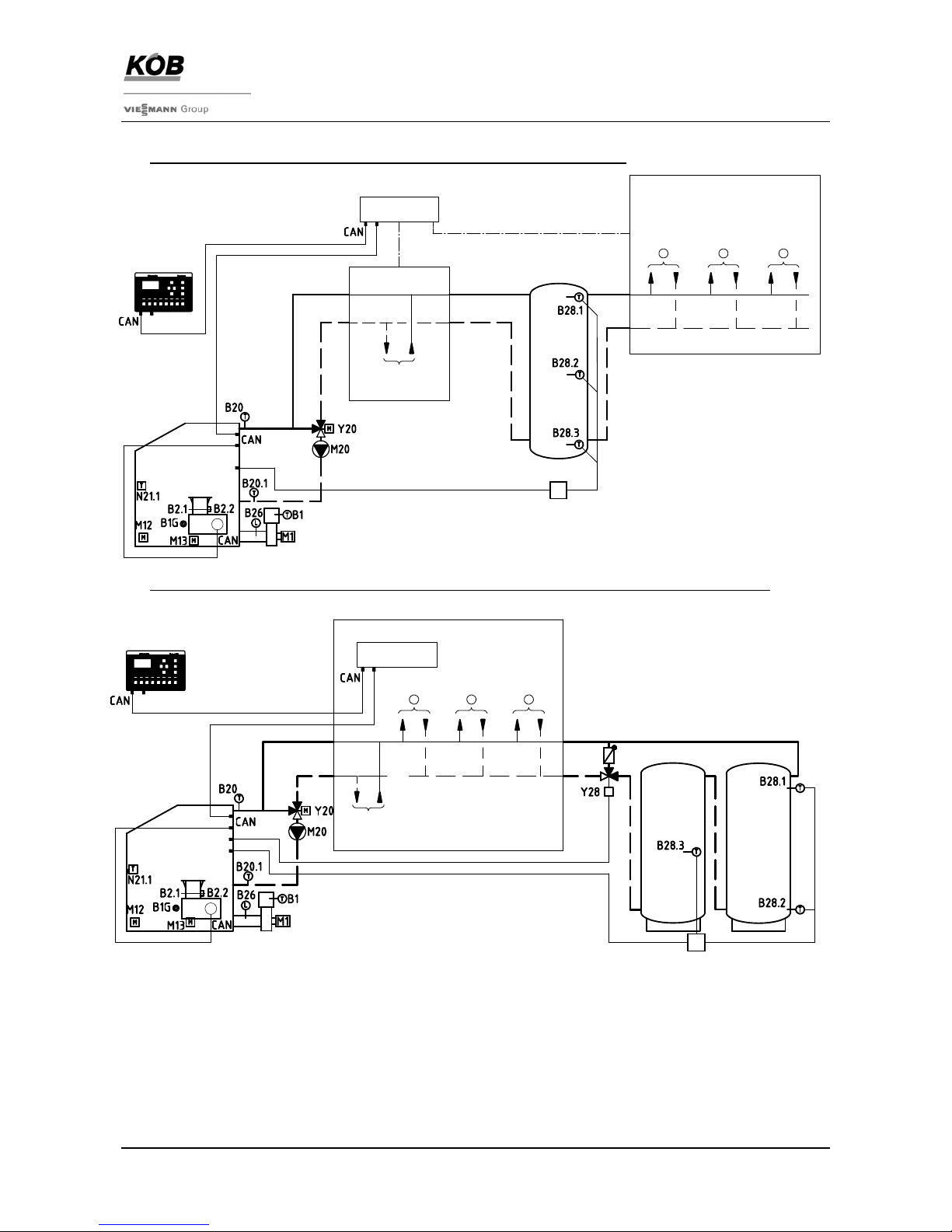
Schematic diagram with ECOTRONIC
a) DYN with reduced log operation (standard with accumulator as hydraulic switcher)
b) DYN with full ECO-function in log operation (accumulator volume as per EN 303-5 – see Spec Sheet 3950)
With this variation, the heat accumulator is incorporated by a storage control valve [Art. No. LSR-DYN-]
ECOTRONIC with heating control unit
The ECOTRONIC can be expanded by a great number of heating control units (heat consumers, auxiliary heat
generators) (refer to spec sheets, Category 4). The operation of the heating control units is all carried out in the control
module for the burner system. Each controller is operated by a separate pushbutton.
For ECOTRONIC expansion possibilities, refer to spec sheets, Category 4
PYROMAT-DYN with integrated heat distributor
One heat distributor with two or three consumer groups can be integrated with the PYROMAT-DYN boiler.
In this design with the manifold attached, the boiler forms a compact overall system (refer to Spec Sheets 4600).
+
F8
OK
-
F7
>
KÖB
F6F5
>
<
F3 F4F1 F2
>
accumulator as
hydraulic switcher
accumulator
additional
heat generator
3
21 heat consumer
control
module
control system module
ECO-RM-00
Pyromat-DYN
control
module
heat consumer
additional
heat generator
123
control system module
ECO-RM-00
accumulator
2accumulator
1
Pyromat-DYN
+
F8
OK
-
F7
>
KÖB
F6F5
>
<
F3 F4F1 F2
>

Spec Sheet
Burner System Loader System
PYROMAT-DYN
1
Köb Holzheizsysteme GmbH, Flotzbachstr. 33, A-6922 Wolfurt, Tel. +43/5574/6770-0, Fax 65707, E-Mail: [email protected]
Subject to technical changes
3010-3
2009-03-01_GB
Technical data:
Trade name Boiler PYROMAT-DYN..
45 65 85
Art. No.: KPM-DYN-45
7387408 KPM-DYN-65
7387860 KPM-DYN-85
7388033
Performance data operation with logs
Nominal heat output [kW] 49 75 100
Max. log length [m] 0.5 0.5 0.5
Firebox volume [l] 185 255 255
Burner efficiency rate [%] 91.7 91.5 91.3
Average exhaust gas temperature [°C] 146 145 144
Performance data automatic operation (chippings)
Maximum nominal heat output [kW] 35 52 70
Minimum nominal heat output [kW] 10 15 20
Burner efficiency rate at nominal load [%] 92.4 92.3 92.3
Electrical connections, total [kW] 1.91 1.91 1.91
Electrical power, ignition device [kW] 1.6 1.6 1.6
Electrical power, exhaust fan [kW] 0.08 0.08 0.15
Electrical power, feed auger [kW] 3 x 400V 0.12 0.12 0.12
Electrical power, de-ashing and cleaning [kW] 0.07 0.07 0.07
Electrical power consumption at max. nominal load [kW] 0.1 0.2 0.3
Electrical power consumption at min. nominal load [kW] 0.04 0.05 0.06
Exhaust gas mass flow, nominal heat output [g/s] 35 56 68
Average exhaust gas temperature at maximum nominal load, °C 138 136 134
Average exhaust gas temperature at minimum nominal load, °C 79 78 77
Maximum water content, forest wood chips [W %] 1) W35 W35 W35
Maximum chip size G50 G50 G50
Heating-relevant specs
Volume on heating gas side [litres] 170 180 190
Volume of ash pan (logs/automatic) [litres] 14 / 34 18 / 43 18 / 43
Max. flue draught, wood [Pa] 2) 25 25 25
Chimney draught required [Pa] 3) +-0 +-0 +-0
Water-bearing resistance (Diff. 10 K) [mbar] 8 16 25
Boiler water volume [l] 130 170 210
Boiler weight without water [kg] 760 935 1065
Test pressure [bar] 5 5 5
Maximum operating pressure [bar] 3 3 3
Maximum boiler temperature [°C] 100 100 100
Minimum return temperature [°C] 70 70 70
Thermic safety outlet: min. flow rate at 2.5 bar [kg/h] 2000 2800 3500
Burner group
Burner pump, Grundfos model RS 30/6 TOP-S 30/7 TOP-S 30/7
Electrical power for pump [W] 49-93 85-195 85-195
Pump output m³/h at mWS 2.5 at 6.5 7.5 at 7.0 7.5 at 7.0
Burner control valve, Siemens model VXG 48.32 VXG 48.32 VXG 48.40
Drive for burner control valve, Siemens SQS 35.00 SQS 35.00 SQS 35.00
Weight of burner group [kg] 14 16 20
1) For function, from W 25 reduction of burner output
2) Maximum overpressure during the start-up phase (chimney cold) in the exhaust pipe after the exhaust blower
3) Do not install a chimney draught controller!

Spec Sheet
Burner System Loader System
PYROMAT-DYN
1
Köb Holzheizsysteme GmbH, Flotzbachstr. 33, A-6922 Wolfurt, Tel. +43/5574/6770-0, Fax 65707, E-Mail: [email protected]
Subject to technical changes
3010-4
2009-03-01_GB
Dimensional drawing:
Feed auger available either left or right turning.
Right design shown
side view (opposite slide-in module)
front view rear view
a
b c
top view

Spec Sheet
Burner System Loader System
PYROMAT-DYN
1
Köb Holzheizsysteme GmbH, Flotzbachstr. 33, A-6922 Wolfurt, Tel. +43/5574/6770-0, Fax 65707, E-Mail: [email protected]
Subject to technical changes
3010-5
2009-03-01_GB
Table of dimensions:
Pyromat-DYN [Art. No.] KPM-DYN-45
7387408 KPM-DYN-65
7387860 KPM-DYN-85
7388033
I Forward flow, connection Bsp R 1¼" R 1¼" R 1½“
II Return flow, connection Bsp R 1¼" R 1¼" R 1½“
III Safety valve Bsp connection R ½“ R ½“ R ½“
IV Sensor for run-off safety valve connection Bsp R ½“ R ½“ R ½“
V Drain valve R ½“ R ½“ R ½“
VI Sight glass (transport hook) connection Bsp R 1“ R 1“ R 1“
A Height of casing 1430 1490 1490
B Width of casing (dismantled) 795 (686) 795 (686) 795 (686)
C Length of casing 958 1163 1313
D Length of exhaust blower 500 500 630
E Filling height 1134 1134 1134
F Height of lid, open 1892 2012 2012
G Radius of ash door 365 365 365
H Outlet, boiler 265 265 265
J Outlet, exhaust blower 175 175 300
M Flange, forward flow, boiler 1331 1389 1386
N Flange, return flow, boiler 811 869 693
O Space for operation 800 800 800
P Min. distance to wall 100 100 100
S Connection for exhaust blower 1) 200 200 200
T Width of firebox 550 550 550
U Depth of firebox 300 400 400
W Outlet, exhaust blower 293 293 293
Z Slide-in module flange 650 765 800
a Connection, boiler 108 108 108
b Connection, boiler 214 214 214
c Connection, boiler 183 183 183
Operation and maintenance
1 Firebox door
2 Ash pan door
3 Cleaning door, top
4 Cleaning door, bottom (slide-in module side)
5 Maintenance cover to radiation chamber
6 Maintenance cover to combustion chamber, automatic (opposite slide-in module)
Electric drives, burner [Art. No. KPM-DYN-..]
10 Drive, de-ashing / Cleaning (opposite slide-in module)
11 Motor-driven air vent (primary and secondary)
12 Motor for exhaust blower
13 Boiler pump
14 Burner control valve with actuating drive
Electric connections and sensors, burner
21 Burner sensor
22 Return circuit sensor
23 Exhaust gas sensor
24 Lambda sensor
25 Burner control panel with temperature-limiting safety switch (TLSS)
26 Sockets for electrical connection
Electric drives and sensors, slide-in module
31 Drive for feed auger
32 Light barrier dosing container
33 Light barrier for combustion chamber
34 Temperature sensor for feed auger
35 Ignition device
1) Reduction up to KPM-DYN-65 is possible (160 mm or 180 mm)
Questo manuale è adatto per i seguenti modelli
3
Indice
Altri manuali KOB Caldaia

KOB
KOB KPT 1250 Series Manuale utente

KOB
KOB KOB PYROMAT ECO SERIES Manuale utente

KOB
KOB PYROMAT ECO 35 Guida rapida

KOB
KOB KOB PYROT KRT SERIES Manuale di istruzioni

KOB
KOB KOB PYROT SERIES Guida rapida

KOB
KOB KOB PYROMAT DYN Manuale

KOB
KOB KOB 7010-1 Manuale del sistema

KOB
KOB PYROT KRT 150 Guida alla risoluzione dei problemi

KOB
KOB KOB PYROMAT DYN Istruzioni per il montaggio