Kobalt 2600503 Manuale utente

Français p. 22
80 V SNOW THROWER
ITEM #0727352
MODEL #2600503
Serial Number Purchase Date
Questions, problems, missing parts? Before returning to your retailer, call our customer
service department at 1-866-456-8934, 9 a.m. - 8 p.m., EST, Monday - Thursday,
9 a.m. - 5 p.m., EST, Friday - Saturday.
AB17560
ATTACH YOUR RECEIPT HERE
1

2
TABLE OF CONTENTS
PRODUCT SPECIFICATIONS
Product Specications............................................................................................................2
Package Contents................................................................................................................3
Hardware Contents...............................................................................................................4
Symbols................................................................................................................................ 5
Safety Information .............................................................................................................7
Preparation ........................................................................................................................... 8
Assembly Instructions ........................................................................................................ 9
Operating Instructions ....................................................................................................... 12
Care and Maintenance........................................................................................................ 15
Troubleshooting........................................................................................................................ 19
Warranty ................................................................................................................................ 20
Replacement Parts List...................................................................................................... 21
SPECIFICATIONS
Type Cordless, battery-operated
Motor 80 V brushless motor
No-load speed 1,900 RPM
Working width 20 in.
Cleaning depth 10 in.
Impeller size 16 in.
Wheels 7 in.
Discharge distance 20 ft.
Weight (without battery) 34.6 lbs.
3
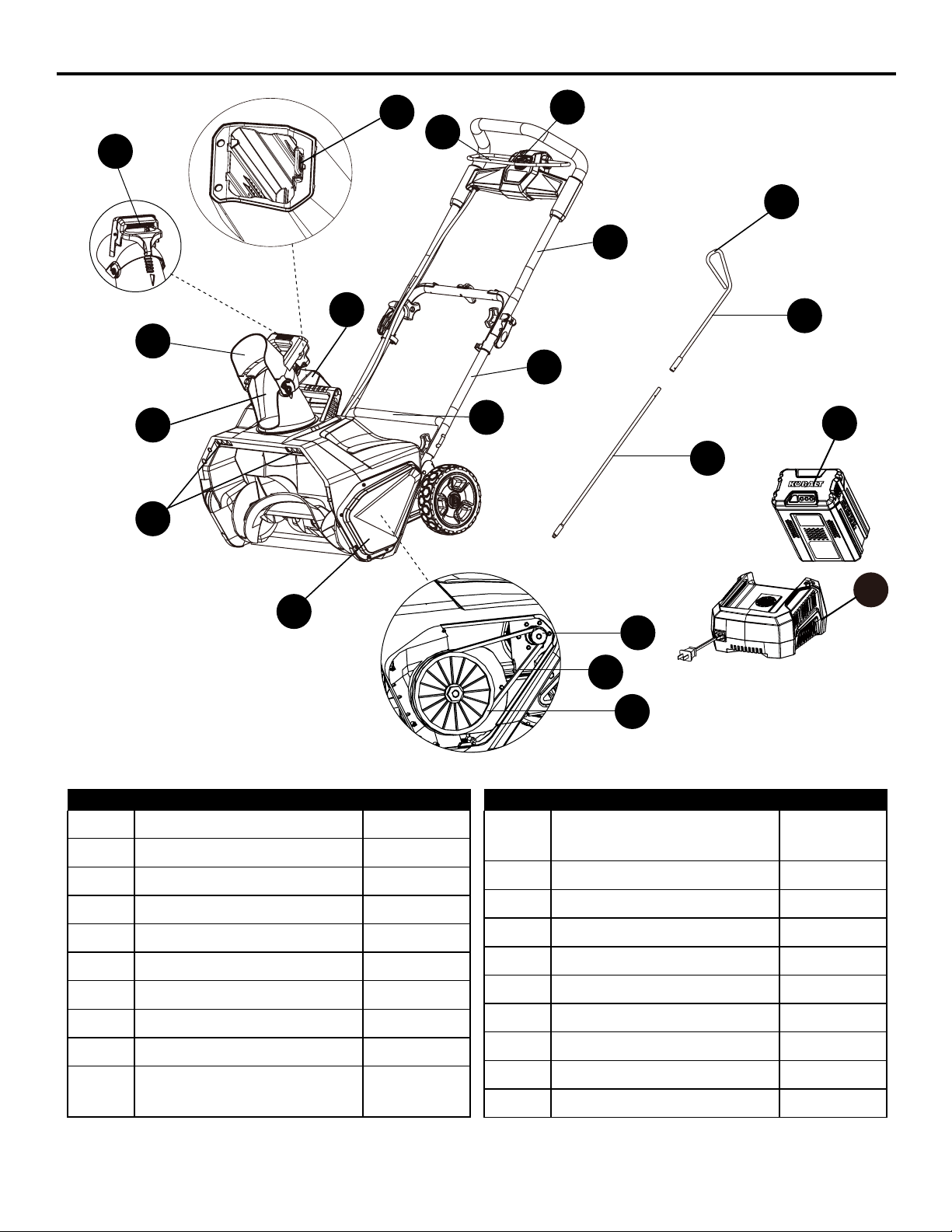
PART DESCRIPTION QUANTITY
AUpper chute control rod 1
BLower chute control rod 1
C Middle handle 1
DUpper handle 1
EChute deector 1
FBattery 1
GCharger 1
HLower handle 1
I Discharge chute 1
JHandle of the chute
control rod
1
PACKAGE CONTENTS
A
B
C
D
E
F
G
PART DESCRIPTION QUANTITY
KBattery compartment
cover
1
L Battery release button 1
M Safety switch button 1
NBail lever 1
OLED lights 1
PTrigger 1
QLeft side cover 1
R Drive Belt 1
SSmall pulley 1
TLarge pulley 1
H
I
J
K
LM
N
O
P
S
R
T
Q
4
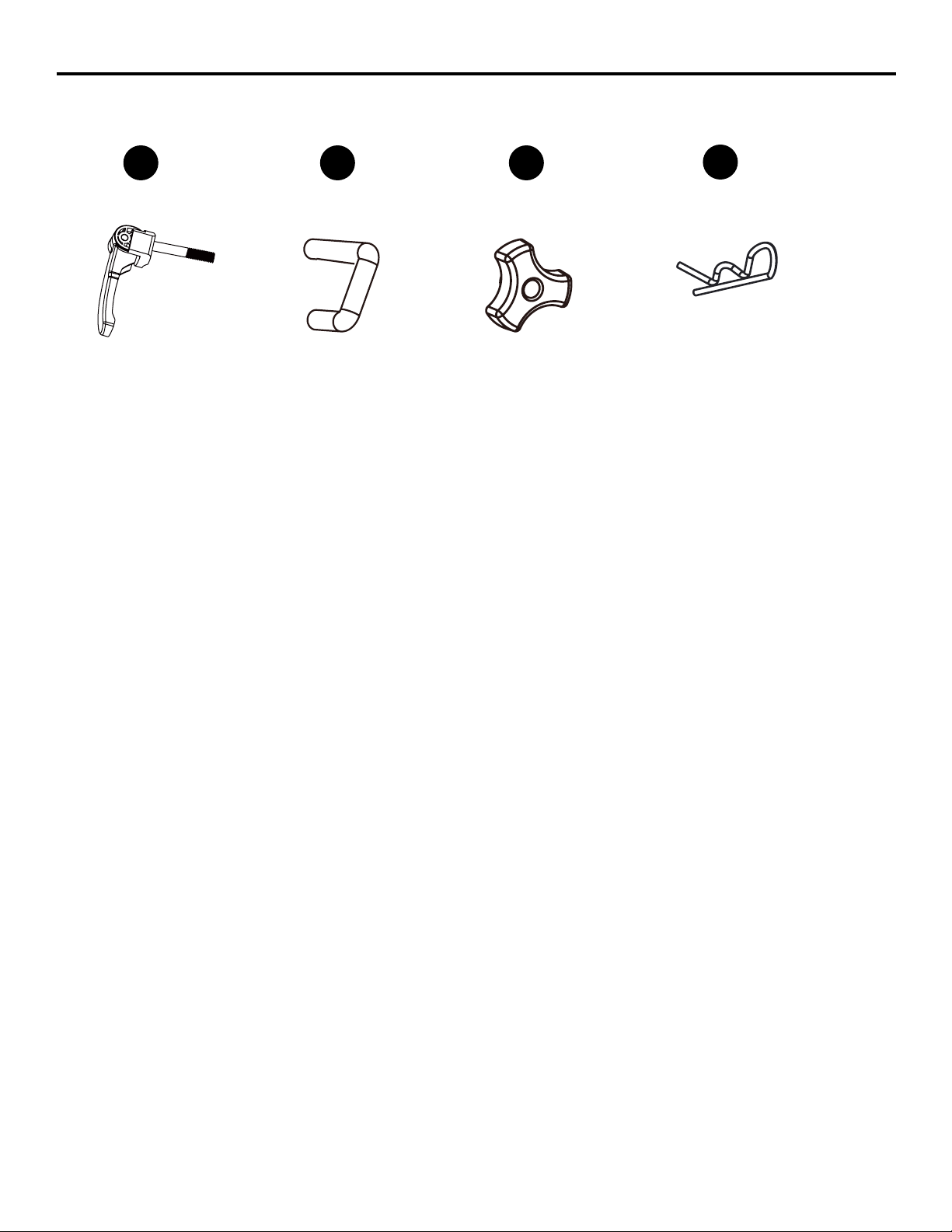
HARDWARE CONTENTS (not shown actual size)
AA
Cam locks
Qty. 2
BB
Bolts
Qty. 2
CC DD
Handle knobs
Qty. 4
Hitch pin
Qty. 1
5
SYMBOLS
Some of the following symbols may be used on this product. Please study them and learn their mean-
ing. Proper interpretation of these symbols will allow you to operate the product better and safer.
SYMBOLS NAME DESIGNATION/EXPLANATION
V Volts Voltage
AAmperes Current
Hz Hertz Frequency (cycles per second)
Wh Watt Hour Energy Storage Capacity
Ah Amp Hour Current Capacity
Direct Current Type or a characteristic of current
RPM Rotating Speed Revolutions per minute
/min Per Minute Revolutions, strokes, surface speed, orbits, etc., per minute
Wet Conditions Alert Do not expose to rain or use in damp locations.
Read The Operator’s
Manual
To reduce the risk of injury, user must read and understand
operator’s manual before using this product.
Eye and Hearing
Protection
Wear eye and hearing protection when operating this
equipment.
Safety Alert Precautions that involve your safety.
Hand and Feet Keep hands and feet away.
Safe Distance Keep bystanders a safe distance from the machine.
Stop the Machine Stop the motor and remove the battery before leaving the
machine.
Moving Parts Stay away from moving parts. Keep all guards and
shields in place.
Thrown objects Thrown objects can ricochet and result in personal injury or
property damage.
Hand and feet Keep hands and feet away from rotating impeller.
Hand Keep hands away from the discharge area.

6
The following signal words and meanings are intended to explain the levels of risk associated
with this product.
WARNING
• To avoid serious personal injury, do not attempt to use this product until you have read this Owner's
Manual thoroughly and understand it completely. If you do not understand the warnings and
instructions in this Owner's Manual, do not use this product.
Call 1-866-456-8934 for assistance.
The operation of any power tool can result in foreign objects being thrown into your eyes, which
can result in severe eye damage. Before operating a power tool, always wear safety goggles,
safety glasses with side shields, or a full face shield when needed. We recommend a Wide
Vision Safety Mask for use over eyeglasses or standard safety glasses with side shields. Always
use eye protection that is marked to comply with ANSI Z87.1.
•
SYMBOL SIGNAL MEANING
DANGER Indicates an imminently hazardous situation, which, if not
avoided, will result in death or serious injury.
WARNING Indicates a potentially hazardous situation, which, if not
avoided, could result in death or serious injury.
CAUTION Indicates a potentially hazardous situation, which, if not
avoided, may result in minor or moderate injury.
CAUTION (Without Safety Alert Symbol) Indicates a situation that may
result in property damage.
SYMBOLS

7
WARNING
SAFETY INFORMATION
Read and understand all instructions before using this product. Failure to follow all instructions listed
below may result in electric shock, re, and/or serious personal injury.
The term “power tool” in all of the warnings listed below refers to your mains-operated (corded) power
tool or battery-operated (cordless) power tool.
• Walk. Do not run.
• Verify that the power tool is not in contact with anything before turning it on.
• Stay away from impeller openings at all times. Keep face, hands, and feet away from concealed,
moving, or rotating parts.
• Be attentive when using the power tool. Stay alert for holes in the terrain and other hidden hazards
or trafc.
• Move up and down slopes when clearing snow. Do not go across a slope. Use caution when
changing direction. Do not use this power tool to clear snow from steep slopes.
• Do not operate the power tool if the guards, plates, and other safety protective devices are not in
place.
• Do not operate the power tool near glass enclosures, automobiles, trucks, window wells, drop-offs,
etc., without properly adjusting the angle of the snow discharge. Keep children and pets away from
the work area.
• Do not operate the power tool at high speeds on slippery surfaces. Look behind when backing up
and exercise caution.
• Wear safety glasses or goggles that meet ANSI Z87.1 standards.
• Use the power tool in daylight or in good articial light.
• To avoid accidental start-ups, remain in the starting position when turning the power tool on. The
operator and the power tool must be in a stable position during start-up. See the section titled
Starting/Stopping Instructions.
• Use this power tool only for the purposes it was designed.
• Hold the power tool with both hands while it is in use. Keep a rm grip on the handles.
• If the impeller does not rotate freely due to ice, thaw the power tool thoroughly before attempting to
use it.
• Keep the impeller clear of debris.
• Do not attempt to clear the impeller while the motor is running.
• After striking a foreign object, turn the power tool off and remove the battery pack, then inspect it for
damage. Repair any damage before restarting and using the power tool.
• If the power tool starts to vibrate abnormally, stop the power tool immediately and attempt to
determine the cause. Vibration is generally an indication of danger.
• Stop the motor and remove the battery pack whenever the operator is not in the operating position,
before unclogging the impeller, and before making any repairs, adjustments, or inspections.
• Do not use on graveled surface unless the power tool is adjusted for such a surface in accordance
with the operator’s manual.
• Keep Children Away – All visitors should be kept a safe distance from work area.
• Dress Properly – Do not wear loose clothing or jewelry. They can be caught in moving parts.
• Wear rubber boots when operating the power tool. Do not operate the equipment when barefoot or
wearing open sandals. Always wear substantial footwear.
• Operation of the power tool in the hand-held position is unsafe, except in accordance with the
special instructions for such use provided in the operator’s manual.

8
SAFETY INFORMATION
• Keep guards in place and in working order.
• Don’t Force Power Tool – It will perform better and safer at the rate for which it was designed.
• Don’t Overreach – Keep proper footing and balance at all times.
• If the power tool strikes a foreign object, follow these steps:
i) Stop the power tool.
ii) Inspect for damage.
iii) Repair any damage before restarting and operating the power tool.
• Store Idle Power Tool Indoors – When not in use, power tools should be stored indoors in a dry,
locked-up place out of reach of children.
• Maintain Power Tools With Care – Follow instructions for lubricating and changing accessories.
• Allow the power tool to run for a few minutes after clearing snow in order to prevent moving parts
from freezing.
• Only use identical replacement parts and accessories for this power tool. The use of nonidentical
parts or accessories could lead to serious injury to the user or damage the power tool, and will void
the warranty.
• Do not pick up the power tool while it is running. The power tool is designed to travel along the
ground.
• Never allow children to operate a power tool. Keep the area of operation clear of all persons,
particularly small children, and pets.
• Thoroughly inspect the area where the equipment is to be used and remove all stones, sticks,
wires, bones, and other foreign objects.
• Stop the blade(s) when crossing gravel drives, walks, or roads.
• Use only 80-volt Kobalt batteries.
• Read the operating and service instruction manual carefully. Be thoroughly familiar with the controls
and the proper use of the equipment.
GENERAL SAFETY RULES
• Verify that the power tool is secure while transporting.
• Store the power tool in a dry area that will prevent unauthorized use or damage. Keep out of the
reach of children.
• Keep handles dry, clean, and free of debris. Clean the power tool after each use. Refer to the
Maintenance Section in this manual for more information.
• If the labels on the power tool become defaced or start to lift off, contact customer service
at 1-866-456-8934.
• Keep these instructions in a safe place for future reference. Refer to them often and use them to
instruct other users. Anyone who uses this power tool must read these instructions carefully.
• Maintain the power tool with care. Follow the instructions for lubricating and changing accessories.
PREPARATION
Before beginning assembly of product, make sure all parts are present. Compare parts with package
contents list and hardware contents list. If any part is missing or damaged, do not attempt to assem-
ble the product.
Estimated Assembly Time: 5 minutes

9
1a. Align the holes on the middle handle (C) and
the lower handle (H). Insert the bolts (BB) and
use the handle knobs (CC) to tighten them.
WARNING
• Do not allow familiarity with this product to make you careless. Remember that a careless fraction
of a second is sufcient to inict serious injury.
• Do not use any attachments or accessories not recommended by the manufacturer of this product.
The use of attachments or accessories not recommended can result in serious personal injury.
1. ASSEMBLING THE HANDLES
ASSEMBLY INSTRUCTIONS
1b
1a
C
H
CC
BB
1b. Align the hole on the middle handle (C) and
the upper handle (D). Insert the cam locks
(AA) and tighten them with the handle knobs
(CC) provided. Once tightened, close the cam
locks to secure them in place.
NOTE: If the upper handle is loose or seperated
from the middle handle, tighten the cam locks and
the handle knobs by turning them clockwise. Do
not overtighten the handle knobs.
C
D
CC AA
10
ASSEMBLY INSTRUCTIONS
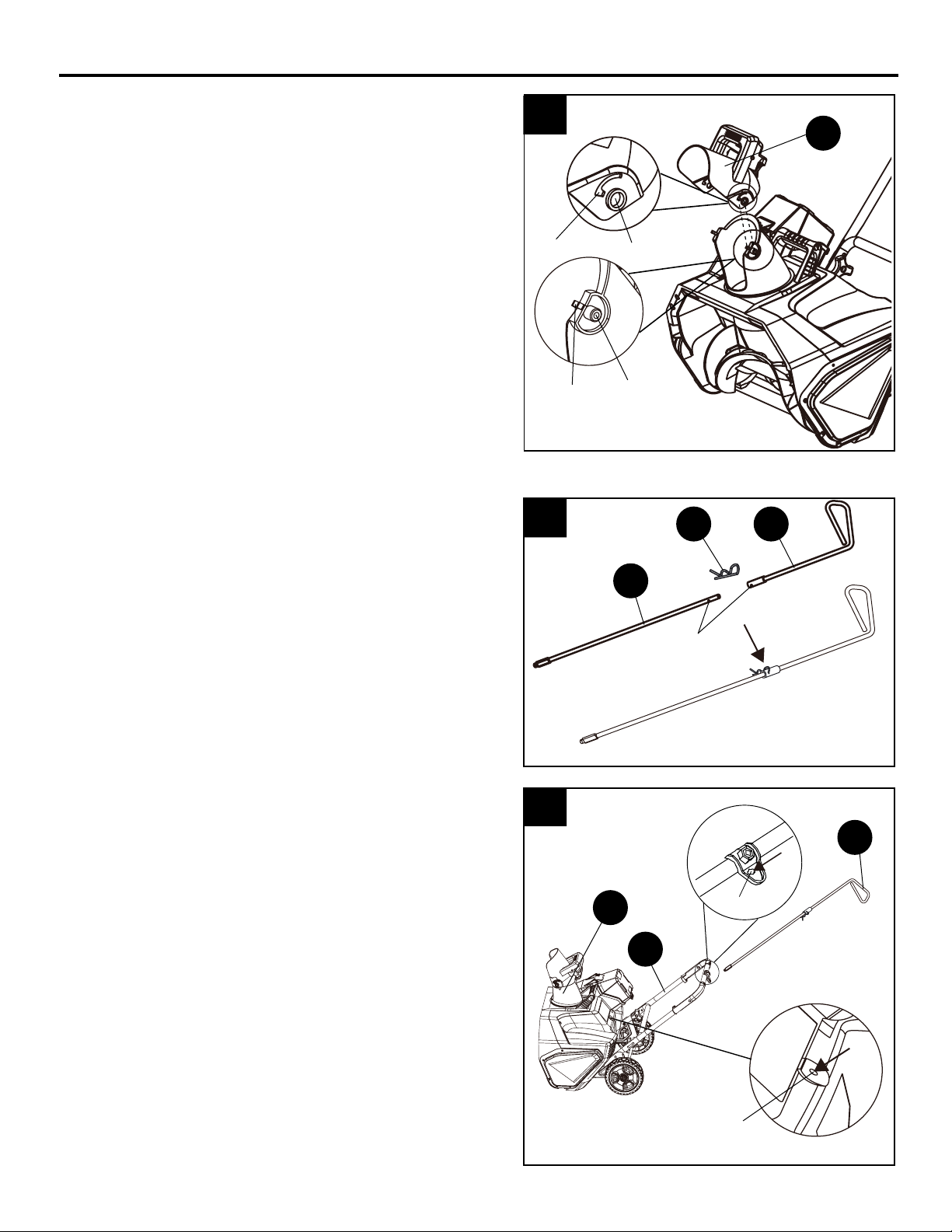
3. INSTALLING THE CHUTE CONTROL ROD
3a. Align the holes on the upper chute control rod
(A) with the holes on the lower chute control
rod (B). Insert the hitch pin (DD).
NOTE: Position the discharge chute (I) so that it
faces forward.
3b. Insert the end of the chute control rod through
the keyed hole in the bracket that is attached
to the top of the middle handle (C).
Ensure that the handle (J) of the chute control
rod points upward and insert the rod into the
keyed hole in the back of the housing.
Firmly push the rod into the keyed hole in the
back of the housing until it snaps into place.
2a E
Latching tab
Keyed holeSlot
Post
2. ASSEMBLING THE DISCHARGE CHUTE
2a. Push the chute deector (E) until the latching
tabs on both sides click into the slots and the
posts on both sides click into the keyed holes.
3a A
B
DD
Holes
3b
IKeyed hole
J
Keyed hole
C
Indice
Lingue:
Altri manuali Kobalt Spazzaneve


