Kohler 13EKOZD Manuale utente

TT-1664 6/15
INSTALLATION INSTRUCTIONS
Original Issue Date: 6/15
Model: 13EKOZD/11EFKOZD, 15EKOZD/13EFKOZD, 16.5/17.5/19.5/20EFKOZD
Market: Marine
Subject: Siphon Break Kit GM94002-KP1 for Sound Shielded Units with Front
Connection Panel
Introduction
Use these instructions to install a siphon break on
sound-shielded generator sets with a front connection
panel. A siphon break prevents seawater entry into the
generator set engine when the engine exhaust manifold
outlet is less than 230 mm (9 in.) above the waterline of
a fully loaded docked or stationary craft.
Read the entire installation procedure. Perform the
steps in the order shown.
Note: Install this siphon break kit on generator sets
equipped with the sound shield kits specified in
Figure 1. Do not install these siphon break kits on
generator sets without sound shields.
Model
Factory
Installed Kit
Field
Installed Kit
13EKOZD/11EFKOZD GM93548-KA1 GM93548-KP1
15EKOZD/13EFKOZD GM93548-KA4 GM93548-KP4
17.5/16.5EFKOZD GM93548-KA2 GM93548-KP2
20/19.5EFKOZD GM93548-KA3 GM93548-KP3
Figure 1 Sound Shield Kits
Safety Precautions
Accidental starting.
Can cause severe injury or death.
Disconnect the battery cables before
working on the generator set.
Remove the negative (--) lead first
when disconnecting the battery.
Reconnect the negative (--) lead last
when reconnecting the battery.
WARNING
Disabling the generator set. Accidental starting can
cause severe injury or death. Before working on the
generator set or equipment connected to the set, disable the
generator set as follows: (1) Press the generator set off/reset
button to shut down the generator set. (2) Disconnect the
power to the battery charger, if equipped. (3) Remove the
battery cables, negative (--) lead first. Reconnect the negative
(--) lead last when reconnecting the battery. Follow these
precautions to prevent the starting of the generator set by the
remote start/stop switch.
Hazardous voltage.
Can cause severe injury or death.
Operate the generator set only when
all guards and electrical enclosures
areinplace.
Moving parts.
WARNING
Servicing the generator set when it is operating. Exposed
moving parts can cause severe injury or death. Keep
hands, feet, hair, clothing, and test leads away from the belts
and pulleys when the generator set is running. Replace
guards, screens, and covers before operating the generator
set.
2TT-1664 6/15
Installation Procedure
1. Remove the generator set from service.
1.1 Press the generator set master control
OFF/RESET button.
1.2 Disconnect the power to the battery charger, if
equipped.
1.3 Disconnect the generator set engine starting
battery, the negative (--) lead first.
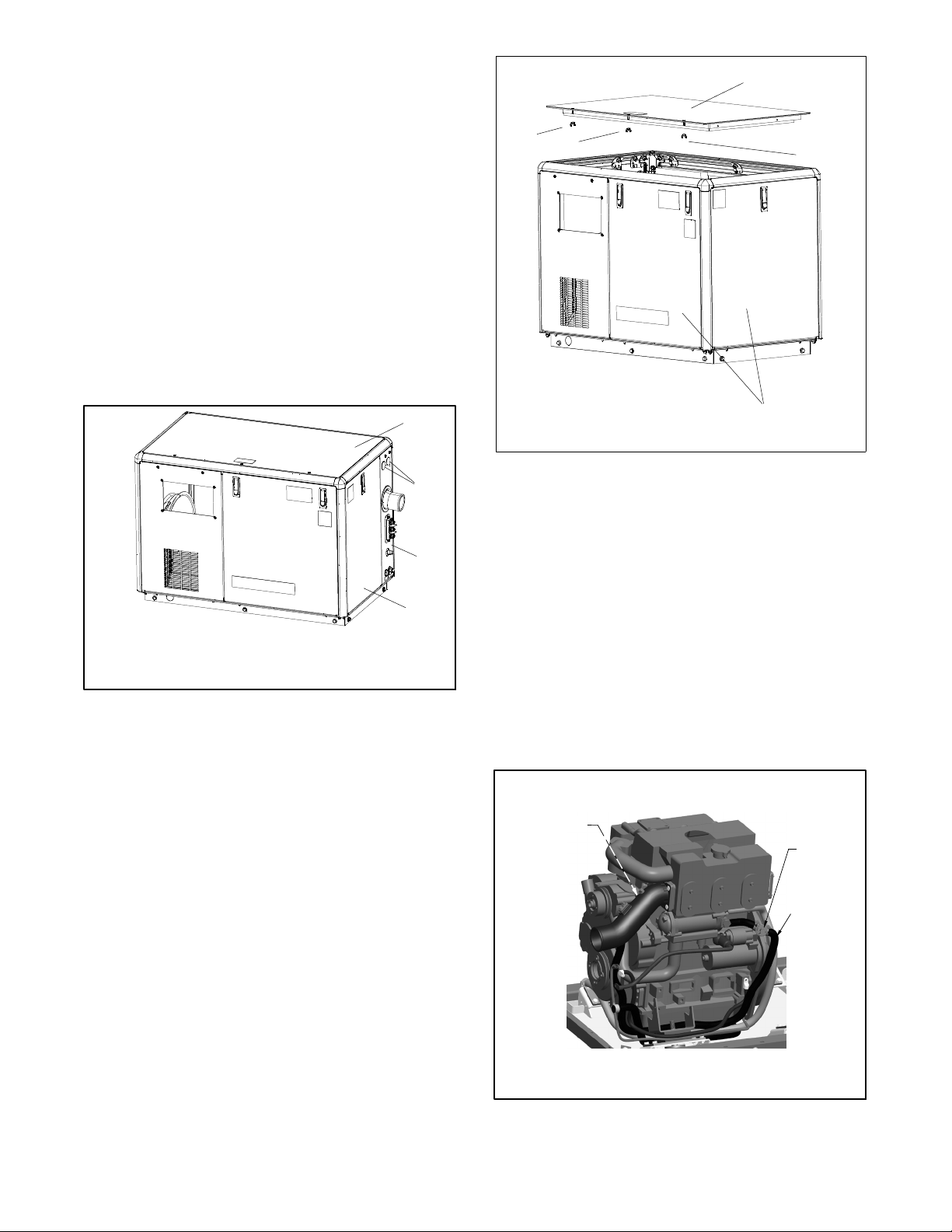
2. Remove the sound shield door and roof.
2.1 Remove the sound shield’s engine-end (front)
door and roof (if necessary) to gain access to the
generator set hoses inside. See Figure 2.
1
1. Engine-end (front) door
2. Customer connection panel
3. Button plugs (qty. 2)
4. Roof
2
3
4
Figure 2 Sound Shield
2.2 Open the service doors.
2.3 Release/untighten the three wing nuts located
underneath the roof. See Figure 3.
2.4 Lift up the roof.
2.5 Slide the roof towards the service side of the unit
for removal.
2.6 Open the front, rear, and non-service side doors
as needed.
1
1. Sound shield roof
2. Wing nut
3. Service door
22
3
2
GM89517
Figure 3 Sound Shield Roof Removal
3. Install the siphon break.
3.1 Remove the 2 button plugs from the customer
connection panel. See Figure 2.
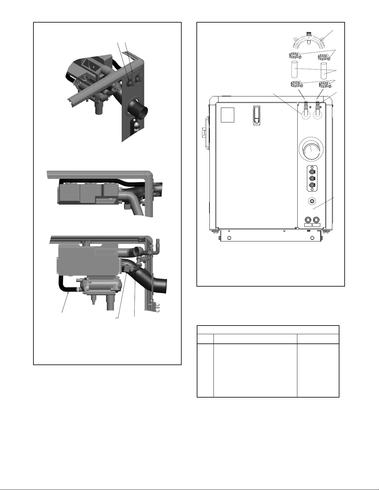
3.2 Install the 2 grommets (X-284-42) and 2 hose
connectors (344934) to the openings in the
customer connection panel. See Figure 8.
3.3 Find and remove the hose (X-312-49) located
between the heat exchanger end cap and the
exhaust mixer. Save the hose clamps, tee, and
pressure switch. Keep the elbow in position on the
exhaust mixer.
Nonservice-Side
View
1. Elbow on exhaust mixer (elbow not shown)
2. Tee, pressure switch, and hose clamps
3. Hose (X-312-49)
1
2
3
Figure 4 Hose Removal

3
TT-1664 6/15
3.4 Secure the molded hose (276206) to the existing
elbow on the exhaust mixer using an existing hose
clamp. See Figure 7.
Note: Cuthosetofit.
3.5 Secure the other end of the molded hose to the
existing tee/pressure switch assembly using an
existing hose clamp.
3.6 Secure the molded hose (276206) to the
tee/pressure switch assembly using an existing
hose clamp.
Note: Cuthosetofit.
3.7 Route the other end of the molded hose to the left
hole in the sound shield’s customer connection
panel. Secure the hose with an existing hose
clamp.
3.8 Secure the hose (X-312-51) to the heat exchanger
end cap. Secure the hose using a hose clamp
(X-426-12). See Figure 7.
3.9 Route the hose from the heat exchanger end cap to
the right hole in the sound shield’s customer
connection panel. Secure the hose with a hose
clamp (X-426-12).
Note: Because of the variety of possible
installations, this kit does not include
hoses to connect to the siphon break. See
Figure 5 for an ID-size hose selection.
Use coolant hoses (SAE 20R1, class B or
equivalent) and hoses suitable for marine
use. Use corrosion-resistant or stainless
steel hose clamps on all fittings.
Kit Number ID-Size Hose, mm (in.)
GM94002-KP1 15.9 (5/8) or 19 (3/4)
Figure 5 Hose Selection
3.10 Determine the required length of hose from each
hose connector to the siphon break. Cut two
pieces of the customer-supplied hose to the
determined length. See Figure 8.
Note: The siphon break must be at least 30 cm
(12 in.) above the waterline during
maximum load and generator shutdown
condition.
3.11 Use the customer-supplied hose clamps to
connect the hoses to the hose connectors. Locate
the hose clamps 12.7 mm (1/2 in.) from each end
of the hose and tighten the clamps. See Figure 8.
3.12 Use customer-supplied hose clamps to connect
the siphon break (GM32985) to the hoses. Locate
the hose clamps 12.7 mm (1/2 in.) from each end
of the hose and tighten the clamps.
3.13 Mount the siphon break to the engine stringer or
other rigid structure. Keep the siphon break reed
valve in a vertical position.
Note: Correct functioning of the reed valve
requires clean operating conditions.
Locate the top of the siphon break (reed
valve) away from possible accumulated
dirt and other contaminants.
Note: To prevent water leakage on the generator
set, do not mount the siphon break over
the generator set.
3.14 Connect the clear flexible plastic tubing
(GM34883) to the siphon break cap using a hose
clamp (X-426-9) to secure. Route the tubing to a
convenient location. This allows the seawater to
drip into the bilge and not on the generator set.
3.15 Siphon break mounting varies with each
application. Generally, use brass or stainless
steel screws and mount the siphon break using
the mounting tabs. Otherwise, use a nylon
(conduit-type) pipe clamp.
Note: Mount the siphon break in a location easily
accessable for inspection and servicing.
Note: Ensure that the siphon break cap is tight
before operating the generator set.
4. Restore the generator set to service.
4.1 Check that the generator set is OFF.
4.2 Reconnect the generator set engine starting
battery, the negative (--) lead last.
4.3 Reconnect the power to the battery charger, if
equipped.
4.4 Start the generator set and check for water leaks.
4.5 Stop the generator set.
4.6 Replace the sound shield’s door and roof.

4TT-1664 6/15
Inspection/Maintenance
Service the siphon break during regular exhaust system
component inspection. See the generator set operation
manual for the service schedule.
Note: The generator set must not be running during the
siphon break inspection.
1. Remove the generator set from service.
1.1 Press the generator set master control
OFF/RESET button.
1.2 Disconnect the power to the battery charger, if
equipped.
1.3 Disconnect the generator set engine starting
battery, the negative (--) lead first.
2. Inspect the siphon break.
2.1 Remove the retaining cap and remove the reed
valve for inspection. See Figure 6.
2.2 Use a mild detergent to remove residue and
oxidation from the reed valve.
2.3 Clear blockage from the reed valve opening.
2.4 Replace the siphon break if the reed valve is
cracked or if the reed valve material has hardened
or deteriorated.
2.5 Install the reed valve into the mounting base with
the valve downward. See Figure 6, item 2.
2.6 Install and only finger tighten the retaining cap. Do
not overtighten it.
1. Cap
2. Siphon reed valve
3. Mounting base
1
2
3
Figure 6 Siphon Break
3. Restore the generator set to service.
3.1 Check that the generator set is OFF.
3.2 Reconnect the generator set engine starting
battery, the negative (--) lead last.
3.3 Reconnect the power to the battery charger, if
equipped.
5
TT-1664 6/15
GM94002-
Engine-End View
1. Round grommets (X-284-42 qty. 2)
2. Hose connectors (344934 qty. 2)
3. Hose (X-312-51) and hose clamps (X-426-12 qty. 2)
4. Use existing elbow on exhaust mixer.
5. Molded hoses (276206 qty. 2). Cut to fit.
5
Top View
12
34
Service-Side View
Figure 7 Hose Locations
2
3
4
5
6
4
1
1. Customer connection panel
2. Hose connectors, qty. 2
3. Grommets, qty. 2
4. Customer-supplied hose clamps
5. Customer-supplied hoses
6. Siphon break valve
Engine-End View
Figure 8 Siphon Break, Installed
Parts List
Siphon Break Kit
Kit: GM94002-KP1
Qty. Description Unique Parts
2Grommet, round X-284-42
2Hose, 0.63 in. ID (10 in.) 276206
1Hose, 0.63 in. ID (34 in.) X-312-51
2Clamp, hose (0.69/1.25 in.) X-426-12
1Valve, siphon break GM32985
2Connector, hose 344934
1Tubing, clear flexible plastic GM34883
1Clamp, hose (0.25/0.70 in.) X-426-9

6TT-1664 6/15
Notes

7
TT-1664 6/15
Notes

8TT-1664 6/15
KOHLER CO., Kohler, Wisconsin 53044 USA
Phone 920-457-4441, Fax 920-459-1646
For the nearest sales and service outlet in the
US and Canada, phone 1-800-544-2444
KOHLERPower.com
Kohler Power Systems
Asia Pacific Headquarters
7 Jurong Pier Road
Singapore 619159
Phone (65) 6264-6422, Fax (65) 6264-6455
Availability is subject to change without notice. Kohler Co. reserves the
right to change the design or specifications without notice and without any
obligation or liability whatsoever. Contact your local Kohlerrgenerator
set distributor for availability.
2015 by Kohler Co. All rights reserved.
Altri manuali per 13EKOZD
1
Questo manuale è adatto per i seguenti modelli
7
Indice
Altri manuali Kohler Equipaggiamento marittimo

Kohler
Kohler 5EOZ Manuale utente

Kohler
Kohler 5ECD Manuale utente

Kohler
Kohler 40EFOZ Manuale utente

Kohler
Kohler GM93516-KP1 Manuale utente

Kohler
Kohler GM31994-KP1 Manuale utente

Kohler
Kohler 5E/4EF Manuale utente

Kohler
Kohler K-9246 Istruzioni per il montaggio

Kohler
Kohler 6EKOD Manuale utente

Kohler
Kohler 150EOZDJ Manuale utente

Kohler
Kohler GM89754-KP2 Manuale utente


