
Konig Security SEC-PCC10 Manuale utente

0
SEC-PCC10 – SEC-PCC20 – SEC-PCC30
PCI SECURITY CARD
ADVANCED
ENGLISH
MANUAL
1
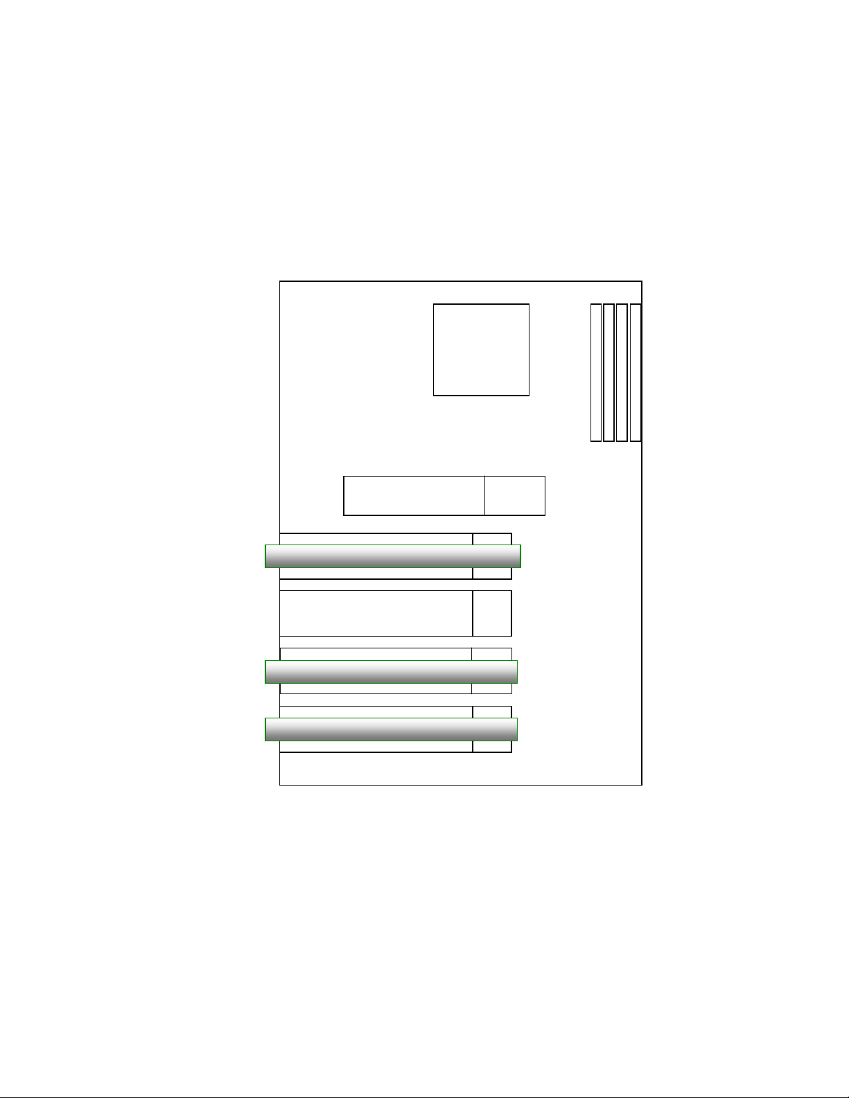
RAM
CPU
AGP
PCI Slot1
PCI Slot2
PCI Slot3
PCI Slot4
Card 2
Card 3
Card 1
Mother board
Installation
1. Turn off the PC’s power and unplug the power cable.
2. Open the PC’s cover and plug the capture card into an empty PCI Slot.
3. Make sure the card is firmly seated and aligned.
Note: When installing multiple cards in a single PC the total video channels may not
exceed 24 cameras. The proper card order is shown as below. The card nearest to
CPU will be the first card. Only card 1 need to be connected for Watch Dog
connection (see following page).

2
Watch Dog Connection
The Watch Dog Connection will allow the card to reboot the PC automatically when it
detects problems with the PC.
A) Connect the reset cable, which is connected with the motherboard, with the Watch
dog connection of the card.
B) Connect the supplied cable with the jumpers on the motherboard and the
Watchdog connection of the card.
See below figure:
4. Replace the PC’s cover and power cord and reboot the system.
5. When the Windows System reboots, the “New Hardware Wizard” dialog will appear.
Ignore the dialogue.
Note: In Windows XP the dialog will disappear after driver installation. In Windows
2000, you will need to close the dialogue manually.
6. Put the Installation CD into the CD-ROM. The Auto-run page will be displayed.
Click on “DVR SYSTEM INSTALL” and then the “DRIVER INSTALL” to automatically
install the driver.
A.PCResetButton
Watch Do g
B. Supplied Watch
Dog cable B. Jumpers on
Mother Board
A. PC reset cable

3
DVR software installation
After the driver has been installed, click “DVR SYSTEM” on the Auto-run page to
install the DVR software.
Note: The first time the DVR software runs, the default user account:
“Administrator” and password “1234” needs to be used to log in to the DVR
System.
Cable connection
Below figure shows the connection cable for camera and audio of the SEC-PCC30.
Connection of SEC-PCC10 (4CH video, 1CH audio) and SEC-PCC20 (8CH video,
2CH audio) are similar.

4
Additional I/O card
Digital I/O card with 4 relay inputs, 3 alarm outputs and a RS485 to RS232 (com port)
converter for PTZ control (model: SEC-PCCDIO suitable for SEC-PCC series)
SEC-PCC30
SEC-PCCDIO
Relay Out 1~3
Alarm Input 1~4
RS-485+
RS-485-
RS-Ground
Connect the Mini Power cable from PC
to J5
To COM Port

5
1. Main Monitor Panel
Name Description
1
Camera Snapshot Click on the number to snapshot the video image of
each channel, the snapshot images will be saved at
“C:\DVR\bin\snapshot”
2
Screen Division
The selection of different screen division layout. (Please
refer to the chapter 3 for detail information)
3
Date/Time The current date and time
4
Message Display the current event
5
Storage Space Indicate the used ratio of total storage space
6
Event Log List The history lists of all the event logged
(Please refer to the chapter 4 for detail information)
7
Alarm On/Off Enable/Disable the audio alarm for video loss
8
Video Backup Click for CD-RW backup dialog
(Please refer to the chapter 5 for detail information)

6
9
Reserved Reserved function
10
Screen lock This function can lock up the monitor screen to prevent
unauthorized access of video
11
P/T/Z Click to switch to the panel for Pan/Tilt/Zoom control
(Please refer to the chapter 6 for detail information)
12
Video Playback Click to switch to the control panel for Video Playback
(Please refer to the chapter 7 for detail information)
13
System Setup Click to get into configuration dialog
(Please refer to the chapter 8 for detail information)
14
Camera Name The name given to the camera.
15
Recorded Time The recorded time of the image
16
Minimum Click to minimize the main panel
17
Exit Button Click to exit this program
2. Screen Division layout select
2.1. Full Screen Display Mode
Click on the “ ” to switch to full screen display mode.
2.2. Sequence Display Mode
Click on the “ ” to display video in sequence mode.
Please refer to “Chapter 8.4 Sequence setting” for the allocation of the video screen
in sequence display mode.
2.3. Select different screen division display mode
Click on other icons for different screen division layout.
※Tips:
Please note that for different screen division layout you can use the right button of the
mouse to select other un-displayed channel as shown below:

7
3. Event Log List Panel
Click on “ ” in main monitoring panel to get into the panel of Event log list:

8
Name Description
1 Events list table List up to 500 events with “Trigger Time”, “Event
Type”, “Sensor ID”, “CCD ID” and “Description”.
Note: an “ ”icon in front of event indicate a
video clip come with the event.
2 Event list search Search events by specifying Trigger Time, Event
Type and CCD ID
3 Return to main panel
Click to return to the main monitor panel
4 Print Image Click to print the current image
Note: Please click pause first before print image
5 Save Image Click to save the current image as Bmp or Jpeg
6 Video playback
control
Stop, Previous frame, Pause, Next frame, play
3.1. Enable video record with the Event log
The user can enable video recording when Motion detected or Sensor detected.
Please refer to “Chapter 8.5 Motion detection setting”and “Chapter 8.6 Sensor
settings” for detail information.
3.2. Pre-alarm recording
Each event is allowed to record video for 3seconds before the event is triggered.
3.3. Video Recording Time with Event triggered
The recording time of each event is 13 seconds.
4. Video Backup
Click on the “ ” in main monitoring panel to get into the configuration dialogue of
video backup:

9
Name Description
1 Video Time Total recorded period
2 Backup Time Time period to be backup into external storage
3 Backup Path Click to browse the backup path of external storage
4 Safe Capacity The Safe Capacity of external storage
5 CD Burning Backup to CD-RW
6 Backup Click to start to backup
4.1. Minimum Safe Capacity
A minimum safe capacity must be specified. The Minimum safe capacity is 500MB.
4.2. CD-Burn software
To ena b l e the CD -Burn function, please install the Nero version 5.5.8.2 or later
version.
5. Playback Panel
Click on the “ ” in main monitoring panel to get into the Playback Panel:
Questo manuale è adatto per i seguenti modelli
2
Indice


