
KRESS CyberCabinet Manuale utente
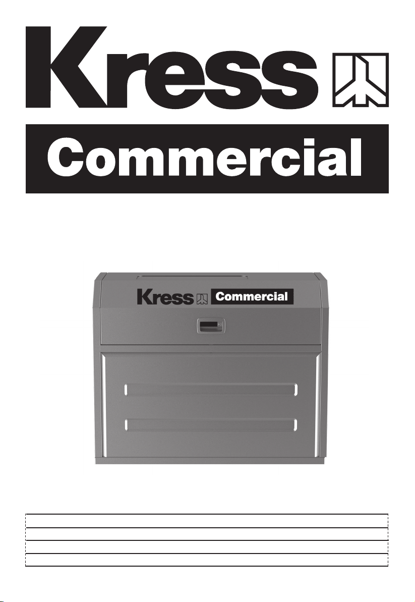
CyberCabinet
CyberCabinet
CyberCabinet
KAC929 KAC929.X
P02
P17
P32
EN
ES
F

2
EN
TABLE OF CONTENTS
Introduction......................................................................................................................................................2
Component List.............................................................................................................................................3
Assembly & Operation.................................................................................................................................5
General layout inside the CyberCabinet...........................................................................................15
Technical Data..............................................................................................................................................16
INTRODUCTION
Dear Customer,
Thank you for buying this Kress Commercial product. We are dedicated to
developing high quality products to meet your commercial landscaping requirements.
The Kress brand is synonymous with premium quality service. Over the years of your
product's life, if you have any questions or concerns about your product, please
contact your dealer or our Customer Service Team for assistance.
We are condent you will enjoy working with your Kress product for years to come.
INTENDED USE
The product is intended for protecting the CyberTank and related products from
inclement weather, accidental contact and theft.
EN
3
2 3 4
1
6
7
5
8
9
10
11
12 13 14 16 17 18
15 19
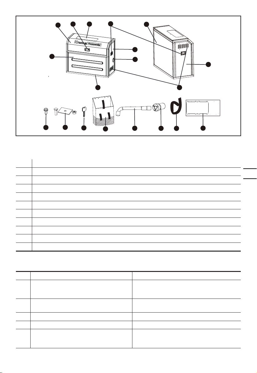
COMPONENT LIST
1.
TOP FRAME & DOOR
2.
PANEL LOCK
3.
OBSERVATION WINDOW
4.
SIDE HANDLES
5.
RIGHT PANEL
6.
FRONT PANEL
7.
CABLE OUTLET
8.
BASE FRAME
9.
BACK PANEL
10.
LEFT PANEL
11.
ADJUSTABLE AIR VENT
ACCESSORY LIST
Description Quantity
12.
Hex Flange Bolt (M5x12)
(For securing the panels and the top frame
& door)
23
13.
Carriage Bolt (3/8-16 x 4'')+Spacer+Nut
(For securing the base frame)
6
14.
Key 2
15.
Bag 1
16.
Socket Wrench
(For assembling or removing the hex flange
bolts)
1
4
EN
17. Customized socket
(For assembling or removing the nuts)
1
18. Cable Tie
7
19. Base Outline
1
20. CyberTank Warming kit*
1
* Not all the accessories illustrated or described are included in standard delivery.
WARNING: This product can expose you to chemicals including lead and Di(2- ethylhexyl)
phthalate (DEHP) which are known to the State of California to cause cancer and birth
defects or other reproductive harm. For more information go to www.P65Warnings.ca.gov.
SAFETY WARNINGS
1. Look for a at and solid surface free from potholes or debris, and place the product on it securely.
2. During rainy or snowy weather, make sure to keep the door closed at all times.
3. In excessively hot and sunny conditions, open both the air vent and the door for better heat dissipation.
4. Do not use the product after consuming alcohol or if you feel unwell.
5. Avoid using this product during thunderstorms or lightning.
6. Do not use the product for purposes other than its intended use.
7. It is recommended to wear gloves and non-slip shoes when operating this product.
8. Remember to wash your hands once all work is completed.
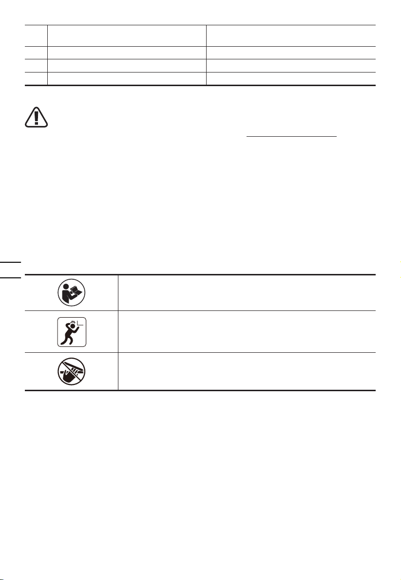
SYMBOLS
To reduce the risk of injury, user must read instruction manual
Mind your head
Be careful not to pinch your hands
EN
5
ASSEMBLY AND OPERATION
• INSTALLING YOUR CYBERCABINET
STEP 1
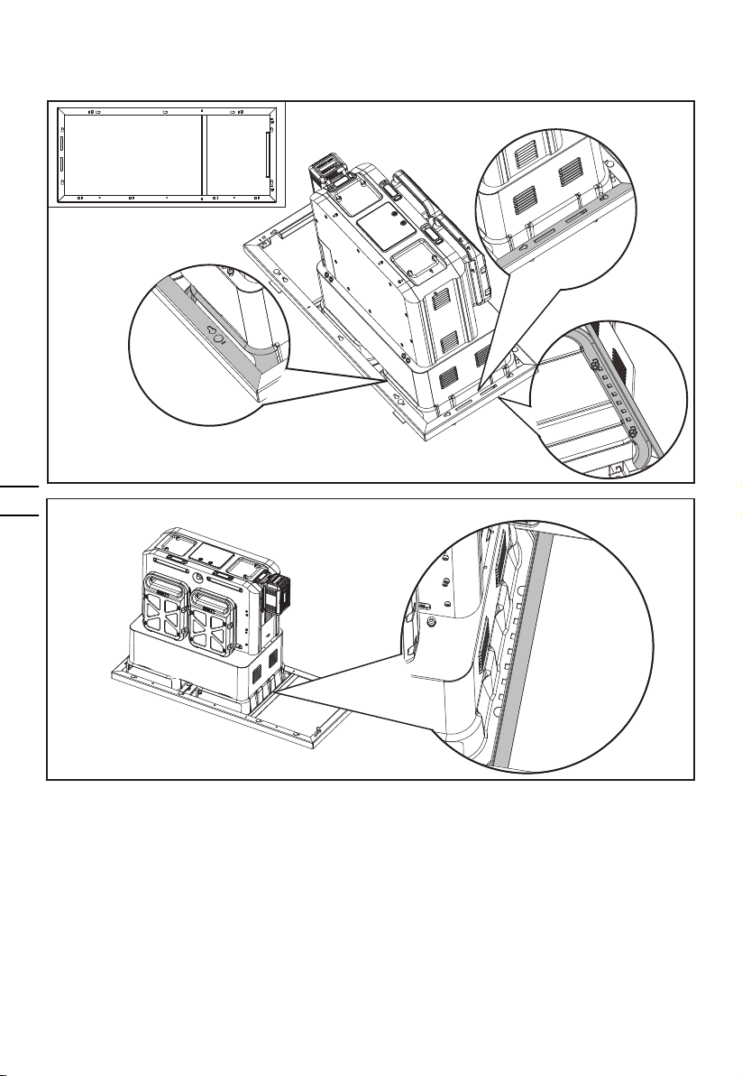
If your CyberTank has already been installed in the preferred location.
- Remove the protective guards of CyberTank. If the rain protection cover is installed, remove it rst.
- Determine the CyberCabinet's installation position based on the location of your CyberTank either in your
truck bed or trailer.
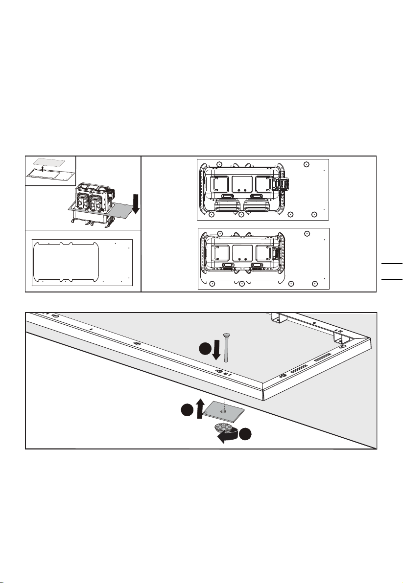
- Place the cabinet base outline on the outside of your CyberTank.
NOTE: The line 1 and line 2 of the base outline should t closely with the CyberTank mounting brackets.
NOTE: Please place the base outline in the correct direction. Do not confuse the front and back of the base
outline. Please pay attention to the printing on the base outline.
- Drill the mounting holes (1/2" / 13 mm) into the truck or trailer as it shows on the base outline.
NOTE: See the following gure for the recommended drilling position of mounting holes. The recommend-
ed drilling position is for reference only which can be adjusted according to the actual situation.
12
34 56
12
34 56
- Place the base frame according to the position of the mounting holes. Fix the base frame with carriage
bolts and nuts.
1
2
1
Line 2
Line 1
6
EN
NOTE:The frame 1 and frame 2 should t closely with the CyberTank mounting bracket. (The base frame
needs to be overlapped with the CyberTank mounting bracket)
There must be a certain gap between frame 3 and CyberTank.
If your CyberTank has NOT been installed
- Read CyberTank installation guide
- Install the CyberTank
NOTE: Do not assemble the protective guards of CyberTank. For detailed information of CyberTank installa-
tion, please refer to CyberTank installation guide.
- Determine the CyberCabinet's installation position based on the location of your CyberTank either in your
truck bed or trailer.
- Place the cabinet base outline on the outside of your CyberTank.
NOTE: The line 1 and line 2 of the base outline should t closely with the CyberTank mounting brackets.
NOTE: Please place the base in the correct direction. Do not confuse the front and back of the base outline.
- Drill the mounting holes (1/2" / 13 mm) into the truck or trailer as it shows on the base outline.
NOTE: See the above gures for the recommended drilling position of mounting holes.
- Place the base frame in the position shown in the gure above. Fix the base frame with carriage bolts and
nuts.
Frame 2
Frame 1 Frame 3
EN
7
STEP 2
Assemble the warming kit with the CyberTank (if required).
When CyberTank is connected with AC cable and it is too cold for Cybertank to charge, the warming kit will
start to warm it up until CyberTank returns to normal status. The LED display of CyberTank will show the
status of warming up.
For detailed information of CyberTank warming kit, please refer to CyberTank warming kit instruction
manual.
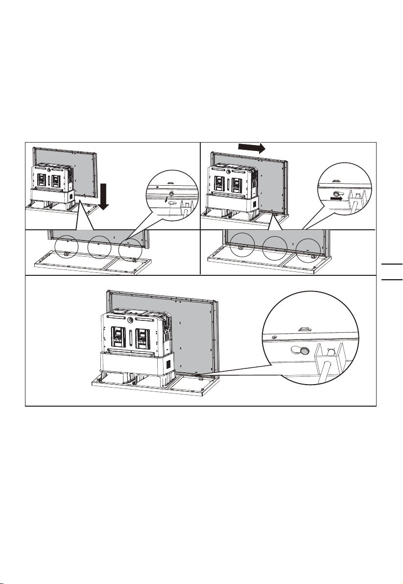
STEP 3
Assemble the back panel with the base frame
8
EN
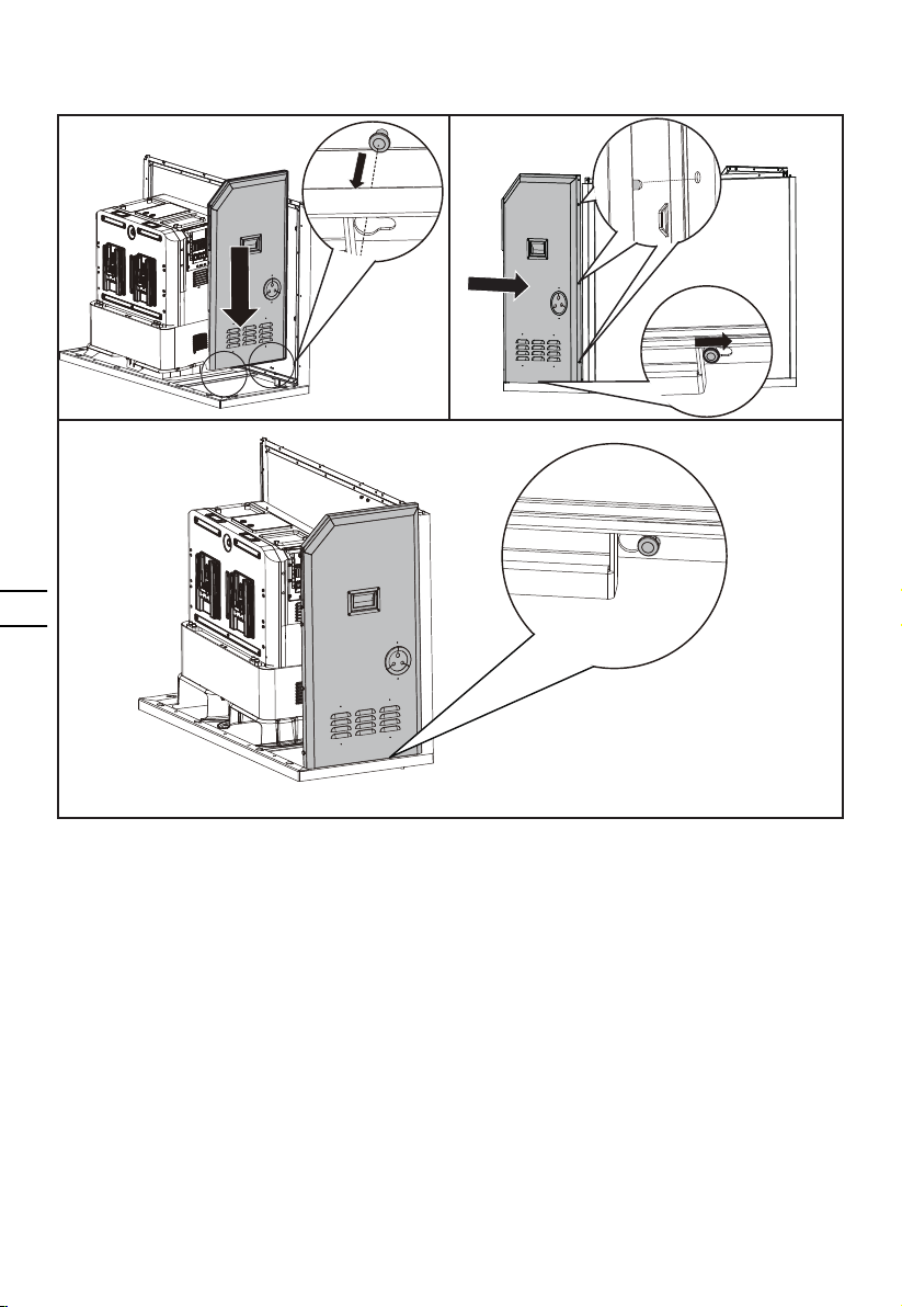
STEP 4
Assemble the right panel.
STEP 5
Assemble the left panel in the same way as the right panel.
EN
9
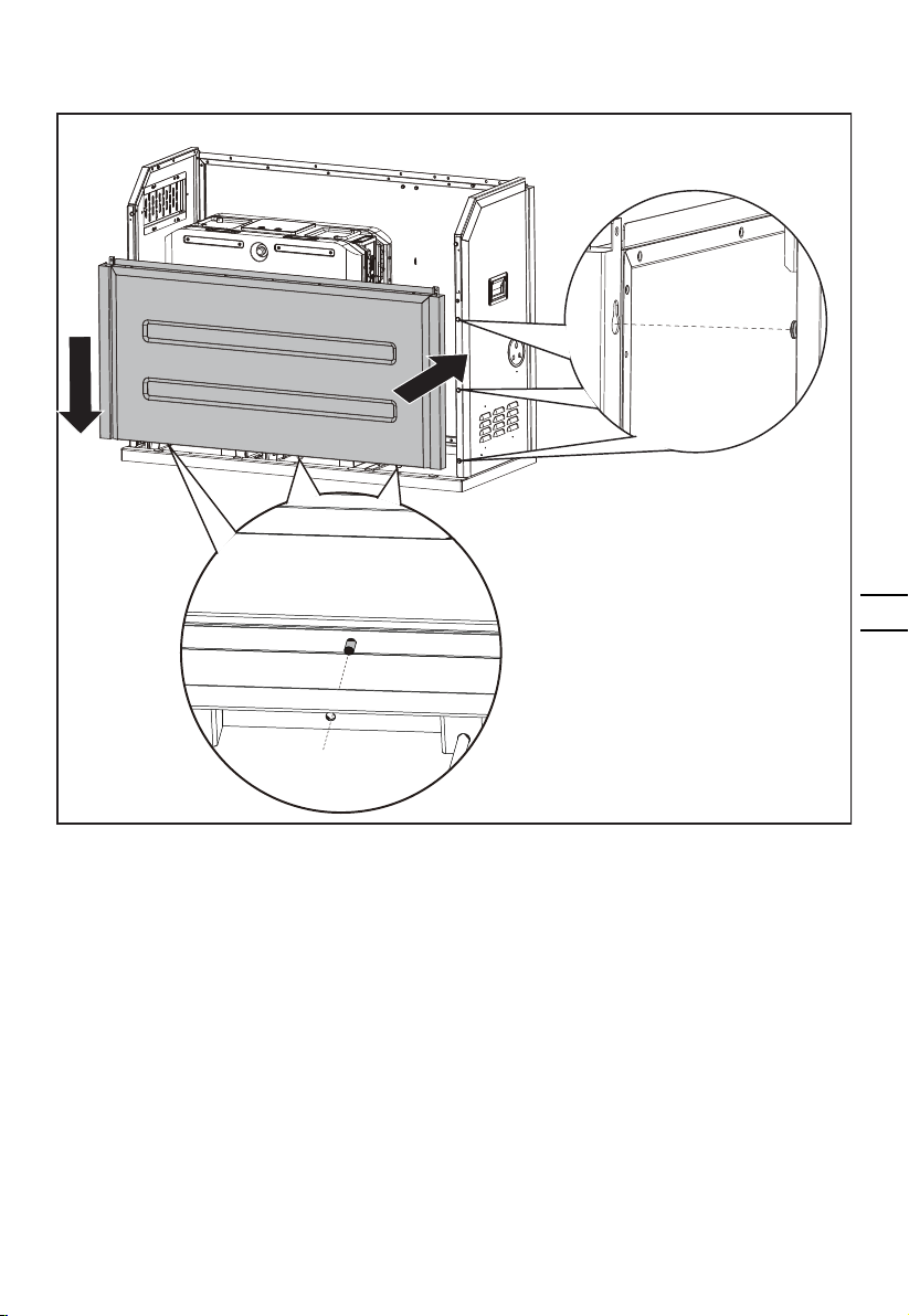
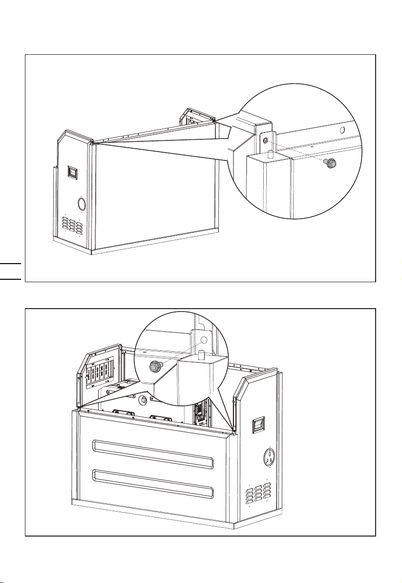
STEP 6
Assemble the front panel.
1
2
10
EN
STEP 7
Secure the right panel and the left panel with hex ange bolts.
Secure the front panel with hex ange bolts.
Questo manuale è adatto per i seguenti modelli
1
Indice
Lingue:
Manuali Stufa popolari di altre marche


Empire Heating Systems
Empire Heating Systems WCC65 Manuale utente

Wetekom
Wetekom 92 86 43 Manuale utente

Desa
Desa SPC170-F Manuale utente

Watlow
Watlow Watrod Electric Tubular Heaters Manuale utente

Haverland
Haverland ECO-DRY GPS Series Manuale elenco delle parti

Stelpro
Stelpro ASILVC2060 Series Manuale utente