KT&C KVR-H410AN Manuale utente
For safe use of system and to prevent product failure or accident, please read this
manual carefully before use.
Ver. H_R1_1.1_ENG

2
Before Usage
This product has been designed and manufactured to assure personal safety. Improper use
can result in electronic shock or fire hazard. The safeguards incorporated in this product will
be protected you if you observe the following procedures for installation, use, and servicing.
This product does not contain any parts that can be repaired by user.
CAUTION
It is strongly recommended that you read this manual and use the product in a proper way
The following might cause a fire
◈Avoid placing the unit near direct sunlight, hear source such as a heater, etc.
◈Do not share the outlet with the other appliances. It might cause an abnormal heating and a fire.
◈When smoke goes up or when you smell a strange smell, stop using the unit and turn the unit off by
unplugging the power cable and contact the customer service center.
◈Place the unit at a distance from a hear source. It is in danger of a fire.
◈Don’t put burning material such as a flammable spray, etc. It may cause a fire.
◈Don’t install the unit at a dusty place. It may cause a fire.
◈Plug the unit firmly not to be shaky. If the plug is not safely inserted into the outlet,
it may cause a fire.
◈When the multi-outlet is used, don’t use several appliances at the same time.
The abnormal heating of the outlet can cause a fire.
◈Don’t damage, modify, bend, twist, pull, stick, or heat the power code and the plug.
◈If the plug is loose in the outlet, don’t use. It can cause a fire or an electric shock.
◈Don’t insert the metals such as a coin, a hair pin, a piece of iron, etc., or flammable material
such as a paper, a matchstick, etc. in the product. It can cause a fire or an electric shock.

3
CONTENTS
1. Summary
Feature …………………………………………………………………………………………………… 6
2. Installation
∙Contents ………………………………………………………………………………………………… 7
∙Rear panel ……………………………………………………………………………………………… 8
∙Video Input……………………………………………………………………………………………… 9
∙Loop Throughout put………………………………………………………………………………… 10
∙VGA output …………………………………………………………………………………………… 10
∙RS-485 connection (PTZ camera)………………………………………………………………… 10
∙RS-485 (Ext. keyboard connection)……………………………………………………………… 11
∙Alarm out connection ………………………………………………………………………………… 11
∙Sensor connection …………………………………………………………………………………… 11
∙RJ-485 port …………………………………………………………………………………………… 12
∙USB port ……………………………………………………………………………………………… 12
∙How to call Setup menu…………………………………………………………………………… 12
3. System configuration
∙Front panel button …………………………………………………………………………………… 13
∙Front direction key …………………………………………………………………………………… 16
∙Mouse…………………………………………………………………………………………………… 17
∙Icon ……………………………………………………………………………………………………… 17
∙How to setup the remote controller ID …………………………………………………………… 18
4. System configuration
∙Information ……………………………………………………………………………………………… 20
∙Date / Time ……………………………………………………………………………………………… 21
∙Password ………………………………………………………………………………………………… 22
∙Disk Manager …………………………………………………………………………………………… 23
∙Upgrade ………………………………………………………………………………………………… 24
∙Button Setup …………………………………………………………………………………………… 25
∙Default Setting ………………………………………………………………………………………… 26
∙Configuration …………………………………………………………………………………………… 26
∙Log out …………………………………………………………………………………………………… 27
5. Record
∙Record……………………………………………………………………………………………………… 27
∙Schedule Record………………………………………………………………………………………… 28
6. N/W Setup
∙IP Address………………………………………………………………………………………………… 31
∙DDNS Option……………………………………………………………………………………………… 33
∙E-Mail
Setup………………………………………………………………………………………………………… 34
∙E-Mail Notification……………………………………………………………………………………… 35
7. Camera Setup

4
∙Camera Setup…………………………………………………………………………………………… 36
∙Camera Title…………………………………………………………………………………………… 37
∙PTZ Setup……………………………………………………………………………………………… 37
∙PTZ Touring…………………………………………………………………………………………… 39
∙How to use PTZ……………………………………………………………………………………… 40
∙Serial port setup……………………………………………………………………………………… 44
8. Display setup
∙OSD……………………………………………………………………………………………………… 45
∙Split Mode……………………………………………………………………………………………… 45
∙Display…………………………………………………………………………………………………… 50
9. Event Setup
∙Sensor …………………………………………………………………………………………………… 50
∙Alarm …………………………………………………………………………………………………… 52
∙Motion Detection ……………………………………………………………………………………… 53
∙Internal buzzer ……………………………………………………………………………………… 54
∙SPOT OUT……………………………………………………………………………………………… 55
∙Audio …………………………………………………………………………………………………… 56
10. Search
∙Search …………………………………………………………………………………………………… 57
∙Calendar search..……………………………………………………………………………………… 58
∙Date/Time search .…………………………………………………………………………………… 59
∙Event search …………………………………………………………………………………………… 59
∙Go To First / Go To Last..…………………………………………………………………………… 60
∙Search control ………………………………………………………………………………………… 60
∙Back-up ………………………………………………………………………………………………… 61
11. Appendix……………………………………………………………………………………………… 64

5
1 —Summary
This Stand Alone Digital Video Recorder is capable of high quality of video and audio data
recording and provides various ways of data search by Calendar, Date/Time and event. Also
the system allows remote user to access in order to monitor and control multiple local DVRs
via TCP/IP / LAN connection.
Main features
(1) High resolution live display
(2) Easy installation and operation
(3) Motion detection record
(4) Sensor and Alarm outputs
(5) Reserved recording (Motion, Sensor/Alarm and time selected record)
(6) Network control via Dynamic IP
(7) NTSC / PAL compatible
(8) Highest data compression of H.264 technology
(9) Data backup to USB memory stick or DVD R/W
Application
(1) Bank, ATM unit, Supermarket, Convenient store and other public places.
(2) Private homes, Apartment, Jewelry shop, Commercial compound and other places
where it needs anti-theft surveillance system.
(3) Warehouse, Production line and other places where evidence is needed after any
event happened and to analyze the situation.
(4) Where to monitor sites remotely
2 —Installation
Feature
Contents
Program CD
HDD fixing screw
(8PCS)
6
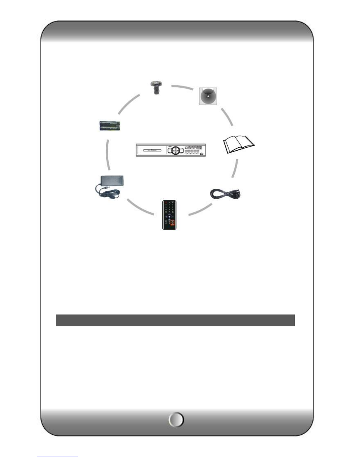
Accessories.
ㆍDigital Video
Recorder (1EA)
ㆍHDD Fixing screw
(8pcs)
ㆍProgram CD (1EA)
ㆍManual (1EA)
ㆍPower code (1EA)
ㆍRemote controller)
ㆍBattery AAA (1.5V 2EA)
ㆍAdaptor (1EA)
[Note] Check the accessories before use.
Rear panel
DIGITAL VIDEO
RECORD
Battery
for
remote
controller
Size :
AAA
1.5V X
2EA
Adaptor
7
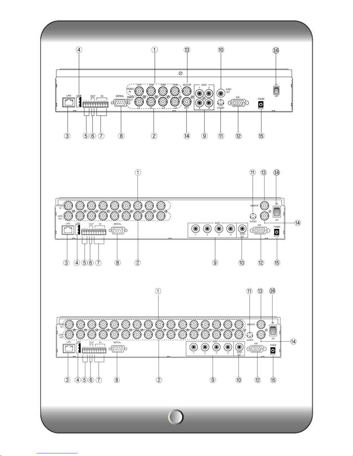
( KVR-H410AN )
( KVR-H920AN )
( KVR-H1640AN )
8
[1] Video Input [2] Loop Through [3] RJ-45(Ethernet) [4] USB 2.0 port
[5] RS-485 [6] Alarm output [7] Sensor Input [8] Serial Port (RS-232)
[9] Audio Input [10] Audio output [11] S-Video [12] VGA Out
[13] Composite Out [14] SPOT OUT [15] Power Input [16] Power switch
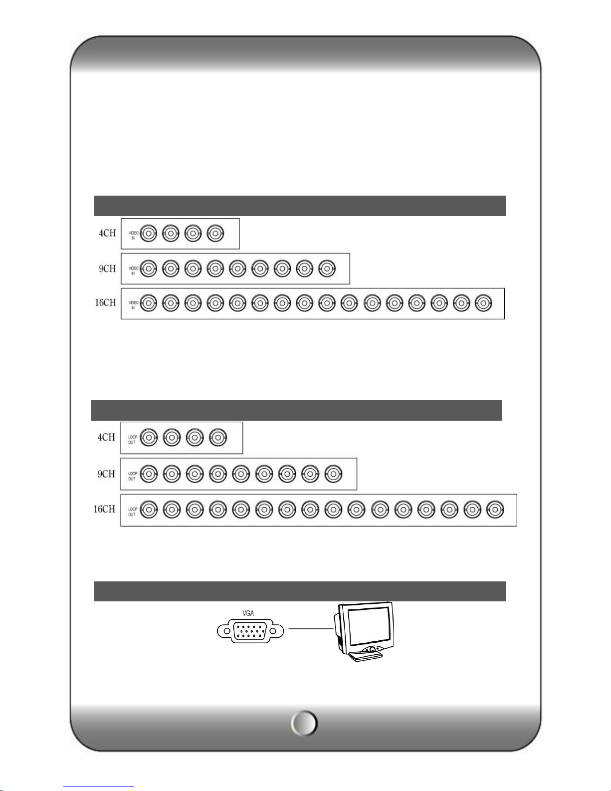
Connect video cable from camera to the BNC connector.
Loop out for each camera image without any image processing or disturbance.
Connect the PC monitor (LCD / CRT).
VGA Output
Video Input
Loop Through Out put
9
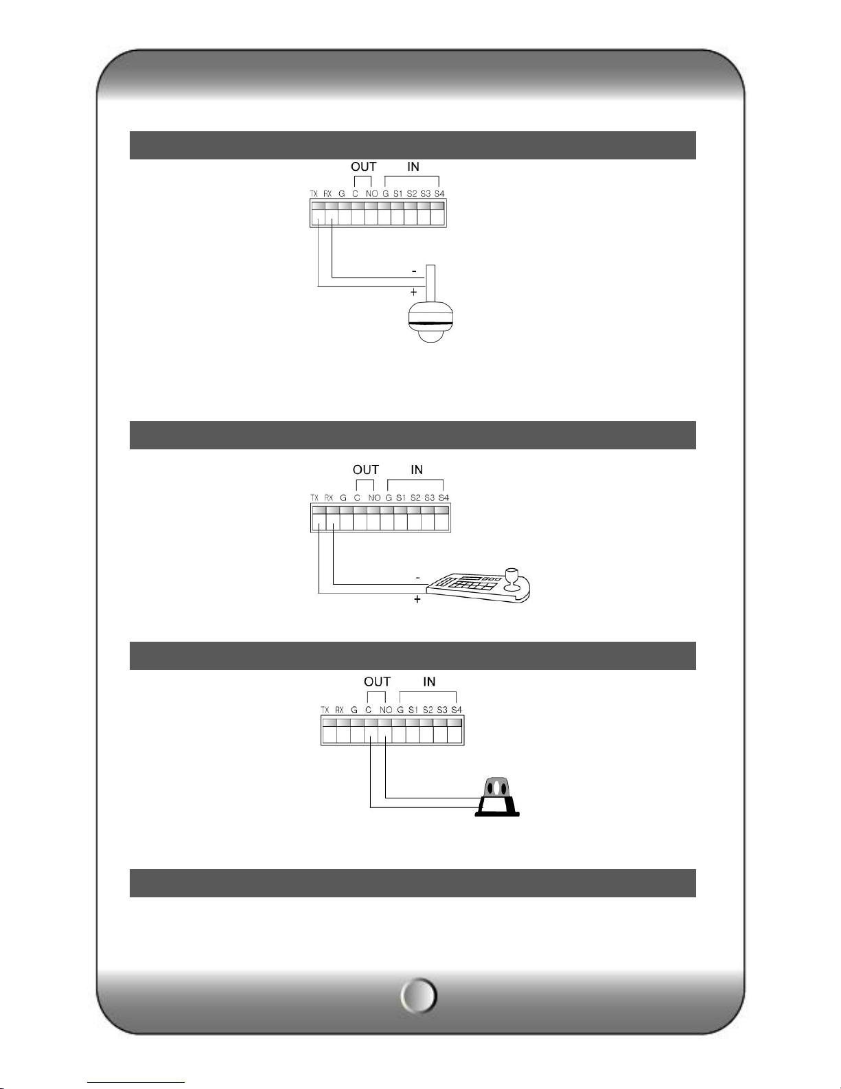
PTZ Camera
Connect the PTZ camera which is supporting its protocol as per the above diagram.
Connect the external keyboard that should be purchased by the DVR manufacturer.
DVR supports 1 alarm output as above diagram.
RS-485 connection (PTZ camera)
RS-485 (External keyboard connection)
Alarm out connection
Sensor connection
10
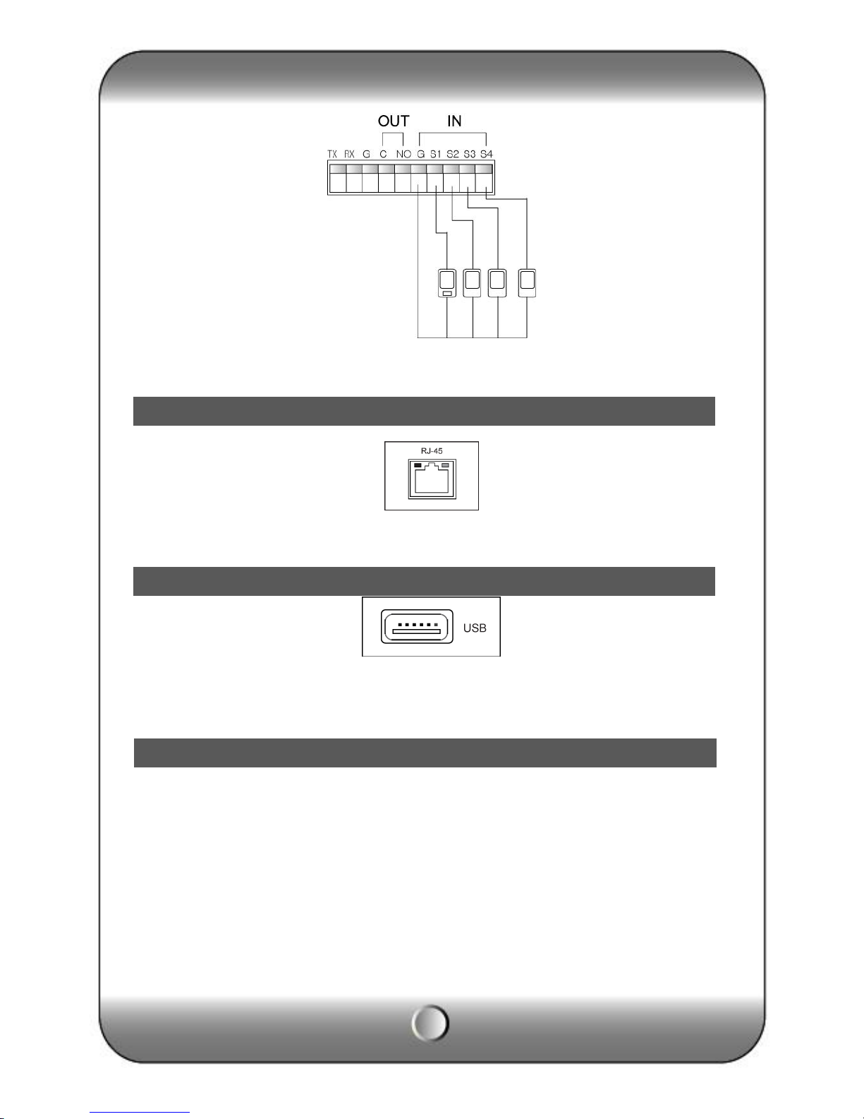
DVR supports 4 Sensor input as above diagram.
The network connection can be made through the 10/100/1000Mb Ethernet connector by RJ-
45.
DVR supports two USB 2.0 port on front and rear panel for mouse control, firmware upgrade
and backup use.
DVR can be operated by using front buttons, remote controller and mouse.
∙By front button
Press “MENU” button.
∙By remote controller
Press “MENU” button on the controller.
∙By mouse
Click the right button of mouse.
RJ-45 port (Internet connection)
USB port
How to call Setup menu
Questo manuale è adatto per i seguenti modelli
2
Indice
Altri manuali KT&C Registratore digitale


