Kystar U6 Manuale utente

U6
Multi-window splicing processor
Version: v3.1
Release date: February 2022
Manual
Beijing KYSTAR Technology Co.,LTD
Professional ultra hd video display,
Control integrated solution providers and operational
service providers
Beijing KYSTAR Technology Co.,LTD
Professional Ultra HD Video Display
Control system integrated solution and service provider

Multi-Image Splicing Processor User Manual
Statement
Thank you for choosing our products.
All rights of the manual are reserved by the company and no copy, delivery, distribution or
storage of any form of the content is allowed without written permission from the company. The
company reserves the right of modifications and improvements of any product function described
in the document without prior notice.
Any possible affiliated control software of the product is only for your usage while all its
rights are reserved by the company. You are allowed to copy the software but only limited to your
personal usage. If the software is to be applied to other purposes, in particular commercial
purposes, please contact us. The company reserves the right of investigate and affix legal
liabilities of any infringement act.
Please read the manual carefully before using. Any improper operation may cause damage to
the product. It is operated with electricity and sufficient attention should be attached. Our
company bears no responsibility for any property loss and personal injury incurred from any
improper operation failing to follow the instructions in the manual. If the provision herein
conflicts with local laws or regulations, the latter shall prevail.
It means that you accept the statement above if you use the product. If not, please contact
with the seller and return the product following relevant procedures.
Certification Description
“CE” Certification
EN 55022:2010
EN 55024:2010
EN 61000-3-3:2013
EN 61000-3-3:2014
EN 0950-1:2006+A11:2009+A1:2010+A12:2011+A2:2013
“FCC” Certification
FCC Part 15
ANSI C63.4:2014
“ROHS” Certification
EPA 3050B:1996,EN1122:2001
EPA 3052:1996,EPA 3060A
EPA 7196,EPA 3540C,EPA 8270C
Version Information
Version: v3.1
Issue Date: February,2022

Multi-Image Splicing Processor User Manual
SAFETY PRECAUTIONS
For your safety, please read this section carefully.
Power
Power supply of the device for normal operation is 100-200V AC.
Please make sure that the product is operated within the voltage range.
High voltage
High voltage devices are contained.
Do not dismantle without professionals
The device is not equipped with repair parts which aimed for
maintenance by customer himself, so do not open chassis and operate
by yourself which may lead to unrecoverable damage of the device. If
maintenance is required, please contact after-sales service personnel.
Assure sound grounding
For your safety, please assure that power line is grounded soundly.
Keep away from strong magnetic field, engine and transformer
For normal operation of the device, please stay away from strong
magnetic field, motor and transformer.
Guard against damp
Keep operational environment dry. If the device becomes damping
inadvertently, do not power the device and use it after being dried.
Keep away from explosives
Please do not use the product in combustible or explosive
environment.

Multi-Image Splicing Processor User Manual
Table of Contents
1. Product Introduction................................................................................ 1
2. Hardware Introduction.............................................................................2
2.1 Front Panel.......................................................................................2
3. Device Debugging................................................................................... 1
3.1 Device Connection.......................................................................... 1
3.2 Debugging Steps..............................................................................2
3.3 Function key:.......................................................错误!未定义书签。
3.4 Advanced Menu...............................................................................8
4. Technical Parameters............................................................................... 9
5. Q&A.........................................................................................................9
Prevent liquid or conductive fragments getting into the chassis
Liquid or metal fragments should be stopped from getting into the
case. If so, the device should be powered off immediately and power
supply can only be allowed after clearance of foreign bodies.

Multi-Image Splicing Processor
1
1. Product Introduction
Multi-screen splicing processor is a high-end video processing equipment
developed and produced by our company for LCD large screen display, performance
and rental, conference room, studio and other markets.The product enjoys the
following features:
1. A maximum of 12 LCD or DLP screens can be joined together
2.8 DVI-U inputs (DVI-U supports DVI/HDMI/VGA/CVBS)
3.8 Arbitrary layout of the screen
4. The front panel has buttons and color display, which can be set quickly without
software installation
5. Support signal echo, you can view input and output signals through software in real
time, what you see is what you get
6. Full 60Hz image processing, smooth picture without tearing
7. Supports output port mapping to achieve blind insertion
8. Between any signal can realize fade-in and fade-out switch
9.1.5U chassis, saving installation space
10. Support one-button black screen
11. Intercept and display any part of the signal source
12. Customize the EDID
13. Can pre-store 32 scene mode, one key call
14 support straight cut and fade out, no black screen, stuck
15. The panel identifies the signal source status

Multi-Image Splicing Processor
2
2. Hardware Introduction
2.1 Front Panel
1POWER: AC 220V POWER switch; ON indicates that the power supply is ON, and
OFF indicates that the power supply is OFF.
2LCD color screen: information display; Displays device and debugging information.
3ADJUST: ADJUST knob; You can select the information in the color screen through the
knob and quickly adjust various parameters, inverseClockwise to decrease, clockwise to increase,
press OK.
4MENU: MENU button, you can enter the main MENU interface for device debugging.
5: navigation buttons; Click to enter the navigation mode.
6INFO: information query button; Example Query the real-time status of input signals.
7WIN: Screen information button; Display screen signal source and switch screen signal
source.
8S1-S4: Signal source button; The input source behind the device is under the main menu
screen, and the parameter input screen is a number1-4
9M1-M4: Shortcut mode call key; Under the main menu interface is the shortcut mode
call button, under the parameter input interface respectively represents the number 5, delete,
number 0, clear.
10 OK: Confirm button to confirm debugging information.
11 : Return or cancel the button.

Multi-Image Splicing Processor
3
12 FUNC: Common function buttons; Click to enter the interface of common functions.
13 MODE:Mode quick call key; Use this key to call mode quickly.
14 S5-S8 :Digital input button; Input sources are displayed under the main menu, and
numbers 6-9 are displayed on the parameter input interface.
2.2 Back panel
1.OUTPUT:Output channel; Contains 12 channels of HDMI output.
2.LAN1 :100 mbit/s network port, connected to the computer network port through the host
computer software debugging equipment.
3.LAN2 :Gigabit network control port; You can debug the device and implement the echo
function.
4.COM:RS232 control port; Connect with the serial port of the computer, debug the equipment
through the upper computer software.
5.INPUT:Input channel; Includes 8 x DVI-U (supports DVI, HDMI, VGA, and CVBS).
6.AC 100-220V:It can be connected to ac power supply of 100-220V.
Multi-Image Splicing Processor
1
3. Device Debugging
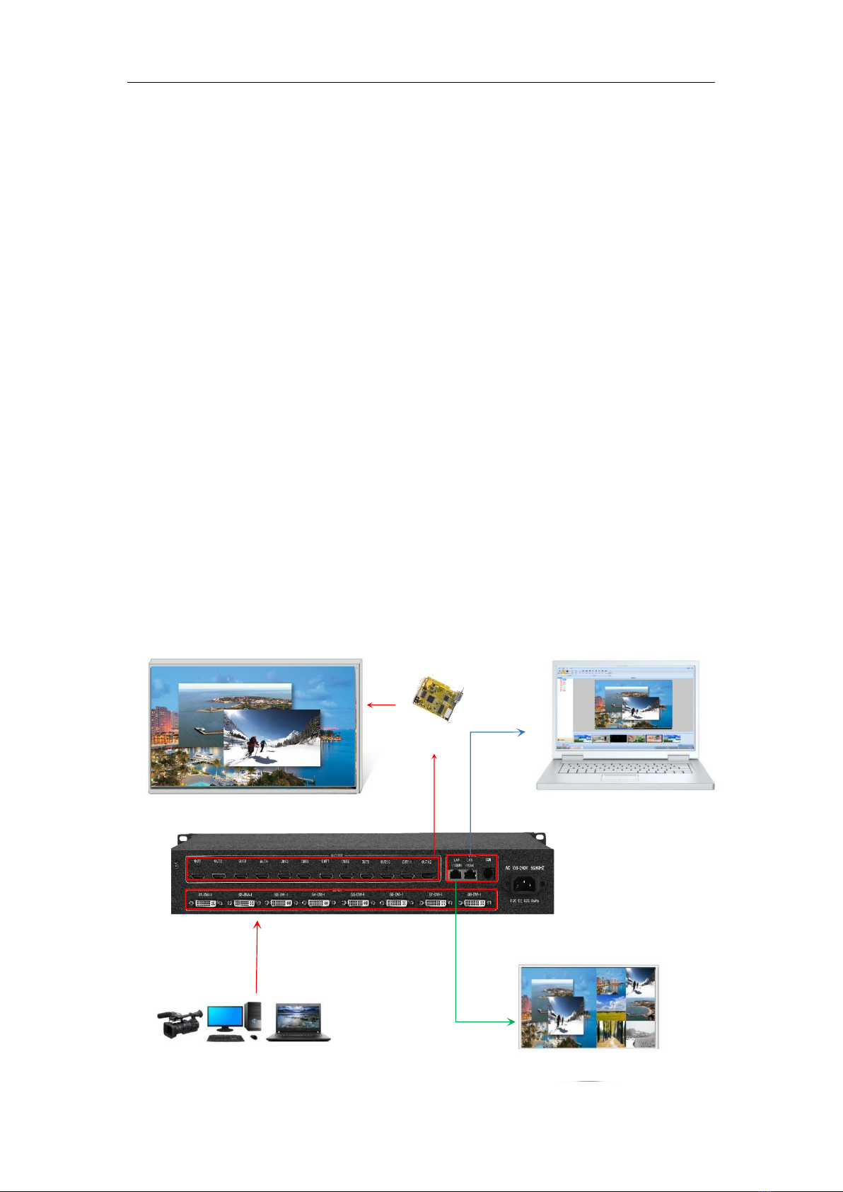
3.1 Device Connection
Device connection could be divided into three parts: power connection, signal
connection and control connection (used for software debugging).
Power connection: device power supply. Connection method: connect power
cord to power plug.
Signal connection: the method transferring signal from signal source to LED
large screen. Connection method: signal source (e.g.: computer)→Splicing Processor
→ Sending cards → Large screen.
Control connection: connect computer with device control port and debug device
connection method. There are three connection methods
(1) Connect 100MB network control port with splicer LAN1 port, which can set
device software.
(2) Connect computer gigabit network port with splicer LAN2 port, which can
not only set device but also echo signal source image.
(3) Connect one crystal head of serial port line which is randomly donated by
device with splicer COM port, and plug DB9 into computer serial port. Any kind of
method among the three can realize device software control.
Connection diagram is as follows:
信 号
千兆回显(可不接)
显 示
控制电脑(可不接)
拼接处理器
发 送
Multi-Image Splicing Processor
2
3.2 Debugging Steps
Step 1:Click "MENU" to enter the main MENU interface, select "Device Mode", and select
the stitching mode of the device: 2X2, 2X3 and other modes.
Note: Select the splicing mode corresponding to LCD display when splicing, and you can
customize the splicing mode
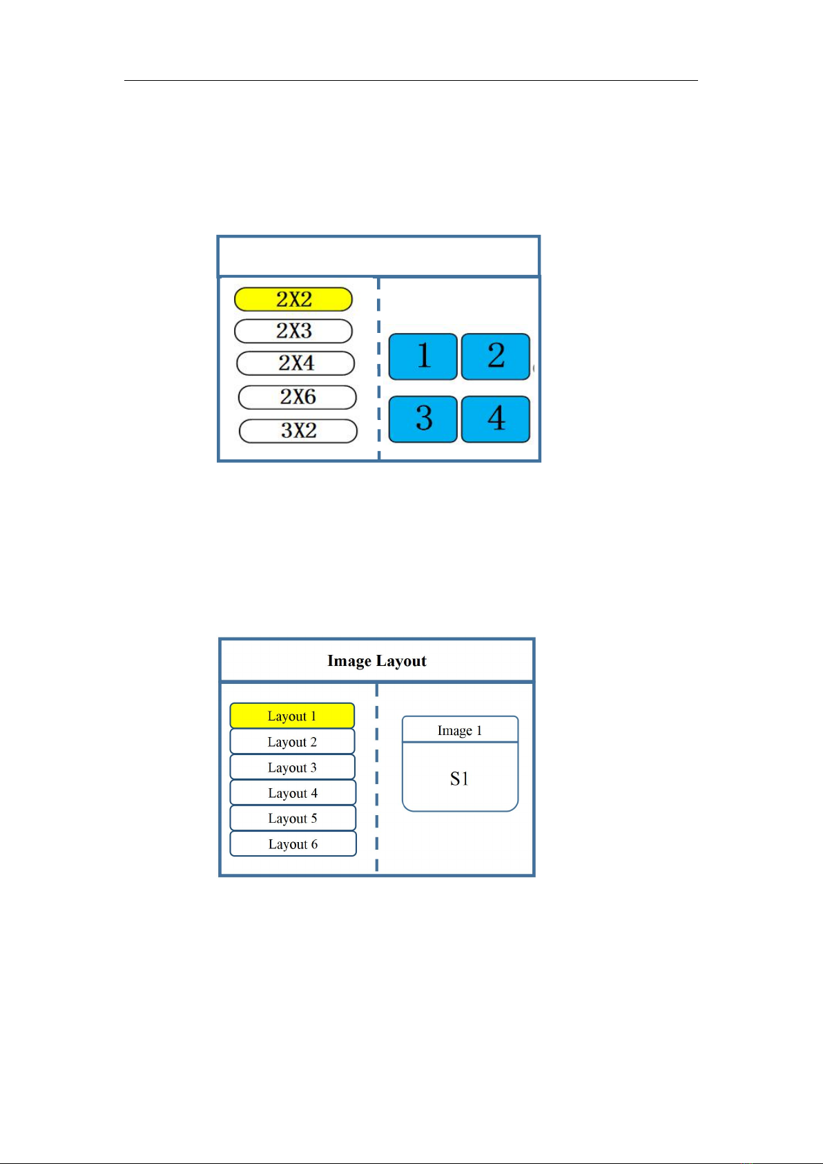
Step 2:Return to the main menu interface, select "Screen Layout", enter the screen number
selection interface, select the number of screens to be set.
Note: this step can be skipped for single screen, as long as the number of screen and project
requirements are consistent for multiple screen, inconsistent layout can be set through the
following operations.
Step 3:Click "MENU" to return to the main MENU, click the corresponding signal source
group on the front panel, select the corresponding signal and click "OK" to confirm.
Device Mode
Copy Output
Horizontal Splicing
Vertical Splicing
Cross Splicing
OUT
Note:
All output displays are
the same.

Multi-Image Splicing Processor
3
Image 1
Image 1
Select by Finger key
Image 2
×1
×10
×100
Image 3
Vertical Size: 1080
Vertical Position: 0
Horizontal Size: 1920
Horizontal Position: 0
Then select the "WIN" button in front to enter the screen switching screen. Select the screen to
switch and click the signal source button on the front panel
.
Step 4: Click "MENU" to return to the main MENU interface, select "Screen Parameters", enter
the image parameter setting interface, set the size and position of each screen
.
Image Parameter
Image 1
Select by Finger key
Image 2
×1
×10
×100
Image 3
Rotate knob to select output
Click “OK”to adjust
Vertical Size: 1080
Vertical Position: 0
Horizontal Size: 1920
Horizontal Position: 0
Note: There are two ways to input numbers:
(1) Adjust by rotating the knob. Adjust the step length by "×1", "×10" and "×100". For
Signal detection: Normal
Sourceresolution:1920*1080
Indice
Altri manuali Kystar Hardware per computer


Manuali Hardware per computer popolari di altre marche

EMC2
EMC2 VNX Series Manuale del proprietario

Panasonic
Panasonic DV0PM20105 Manuale utente

Mitsubishi Electric
Mitsubishi Electric Q81BD-J61BT11 Manuale utente

Gigabyte
Gigabyte B660M DS3H AX DDR4 Manuale utente

Raidon
Raidon iT2300 Manuale utente

National Instruments
National Instruments PXI-8186 Manuale utente


