
Lacanche LAG 010 CKG Guida alla configurazione
Page 1 sur 18– Ft010CKG – US – Date de mise à jour : 26/02/10 - Indice : 01
LAG 010 CKG
-Do not store or use gasoline or other flammable vapors and
liquids in the vicinity of this or any other appliance.
-WHAT TO DO IF YOU SMELL GAS.
•Do not try to light any appliance.
•Do not touch any electrical switch.
•Do not use any phone in your building.
•Immediately call your gas supplier from a neighbor’s phone.
Follow the gas supplier’s instructions.
•If you cannot reach your gas supplier, call the fire
department.
-Installation and service must be performed by a qualified
installer, service agency or the gas supplier.
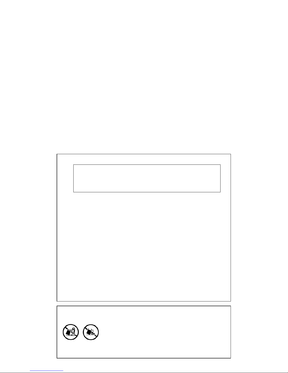
WARNING :
THIS RANGE CAN TIP
INJURY TO PERSONS COULD RESULT
INSTALL ANTI-TIP DEVICE PACKED
WITH RANGE
SEE INSTALLATION INSTRUCTIONS
"OPTION GRILL "
WARNING : If the information in this manual is not
followed exactly, a fire or explosion may result causing
property damage, personal injury or death.
Page 2 sur 18– Ft010CKG – US – Date de mise à jour : 26/02/10 - Indice : 01
GENERAL MANUAL
LAG 010 CKG
Page 3 sur 18– Ft010CKG – US – Date de mise à jour : 26/02/10 - Indice : 01
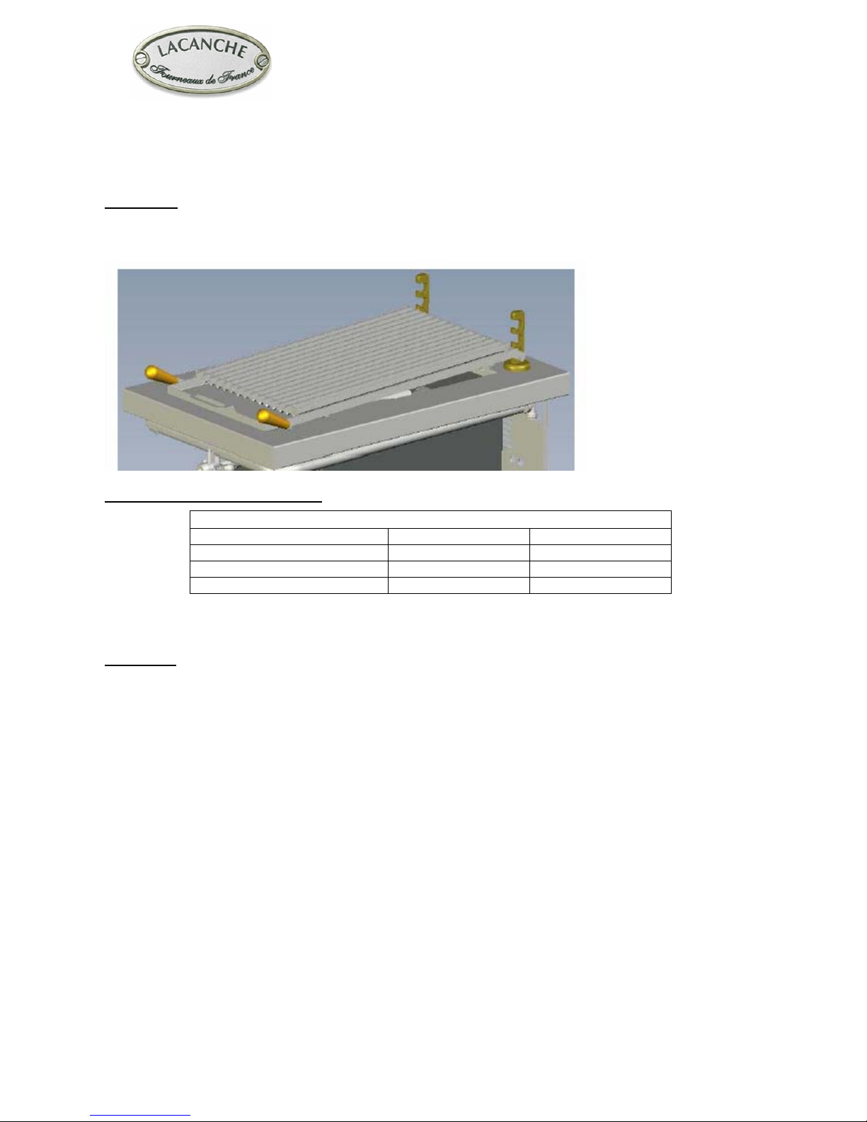
Layout :
Cooktop option lava rock grill left or right of central hob (depending on model)
Description :
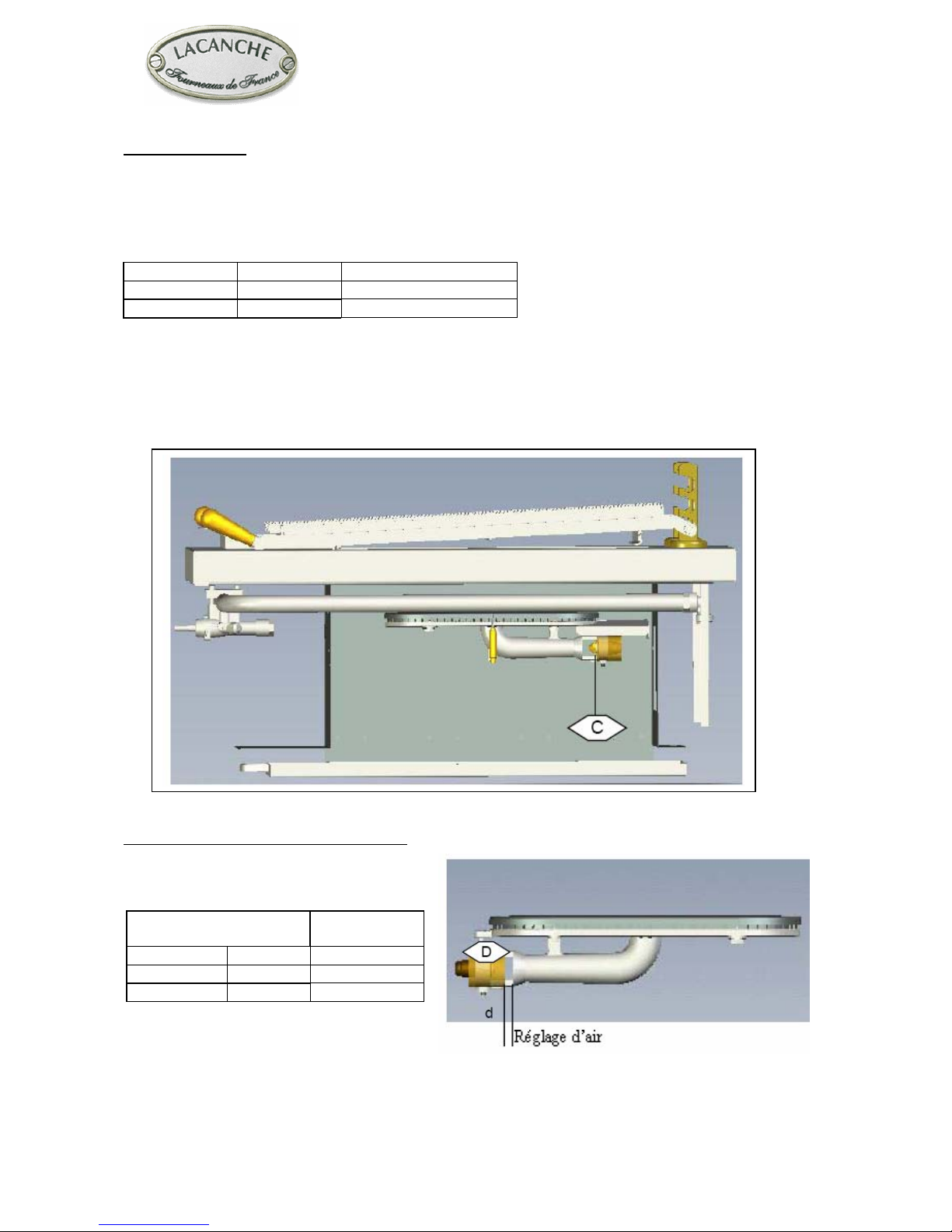
A 12,500 BTU/hr gas burner, a gas valve with thermocouple safety is located under de fire tray.
A 275 x 460 mm grill resting on pillars is located above the fire tray.
Electric ignition..
Pressures and hourly consumption :
Table 1
PRESSURE 6’’ WC 10’’ WC
GAS Natural gas G.P.L.
Btu / hr Btu / hr
12,500 12,500
Accessories
Cooking grill.
Ash-drawer
Bag of lava rock.
Page 4 sur 18– Ft010CKG – US – Date de mise à jour : 26/02/10 - Indice : 01
Page 5 sur 18– Ft010CKG – US – Date de mise à jour : 26/02/10 - Indice : 01
"OPTION GRILL"
INSTALLER'S MANUAL
Appliances must be installed in a workmanlike manner in
accordance with the instructions in this manual and locally
applicable regulations.
This manual will be handed over to the user after
installation.
Page 6 sur 18– Ft010CKG – US – Date de mise à jour : 26/02/10 - Indice : 01
INSTALLER’S MANUAL
LAG 010 CKG
Page 7 sur 18– Ft010CKG – US – Date de mise à jour : 26/02/10 - Indice : 01
SITTING
Cautions :
The purchaser undertakes to install or arrange for his/her equipment to be installed in a workmanlike manner and in
accordance with the applicable regulations and standards.
Any servicing or repair work on appliance must be performed by a qualified technician.
Recommendations :
Adjust this appliance by using the levelling feet. Allow a minimum clearance of 50 mm between the appliance and
any other surfaces (walls affected by heat).
If the appliance is to be built in between two surfaces, it is CRUCIAL to allow free circulation of air behind the
appliance (provide shielding at rear). Cooktops should NEVER be installed lower than adjacent worksurfaces. It is
also recommended to allow the unit front panel to protrude 50 mm relative to the adjacent units.
Must be installed under an exhaust hood.
Do not install this unit near combustible walls, partitions, pieces of furniture or decorative material unless these are
covered with adequate thermal insulation of the noncombustible type. Making sure the resulting installation meets
local fire regulations.
A shut-off valve must be installed and accessible close to the appliance in order to isolate it from the supply or to
facilitate cutting the gas supply :
INSTALLER’S MANUAL
LAG 010 CKG
Page 8 sur 18– Ft010CKG – US – Date de mise à jour : 26/02/10 - Indice : 01
Changing nozzle :
Replace the injector.
Lacanche ranges are supplied with the gas fi tting requested when the order is placed. The settings must
be fi ne-tuned when the range is installed.
IMPORTANT : Close the mains gas valve before carrying out any works.
GAS Pressure Ø
Natural gas 6" WC 1.40
L.P. propane 10" WC 0.95
IMPORTANT
In case of use with a gas other than that for which the appliance was initially set up, it is crucial
replace the injectors and modify the adjustments as defi ned below.
Adjusting the primary air of hob burners
Loosen the screw that secures the air ring D
Adjust the air ring.
Opening in mm /
inches
GAS Pressure Oven
Natural gas 6" WC 4 / 3/16
L.P. propane 10" WC 6 / 1/4
INSTALLER’S MANUAL
LAG 010 CKG
Page 9 sur 18– Ft010CKG – US – Date de mise à jour : 26/02/10 - Indice : 01
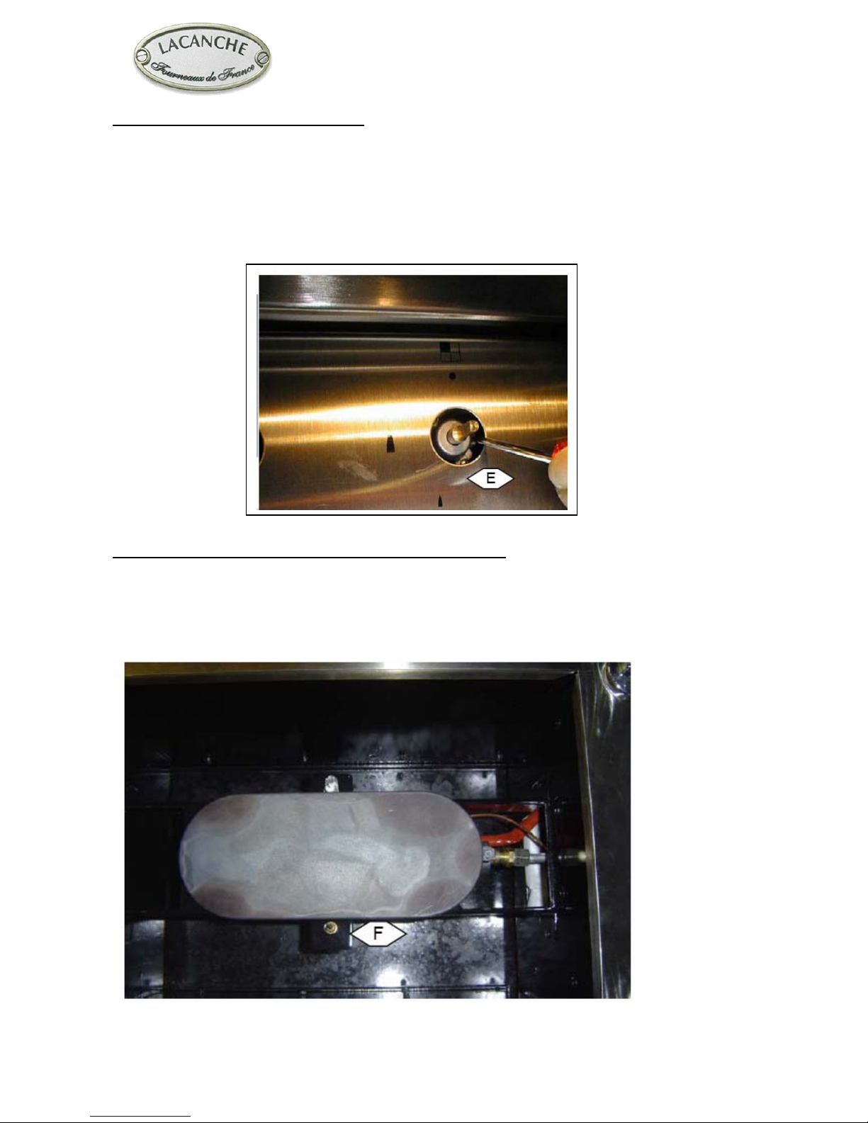
Adjusting reduced flow of hob burners :
After connection or change of gas, it is crucial to modify this adjustment :
►Remove the knob.
►Light the appropriate burner.
►Adjust to minimum setting.
►Use a small screwdriver to set the adjusting screw E.
N.B : Flame is reduced to ¼ of its size in the minimum setting, the burner must remain lit when changing
from maximum setting to minimum setting.
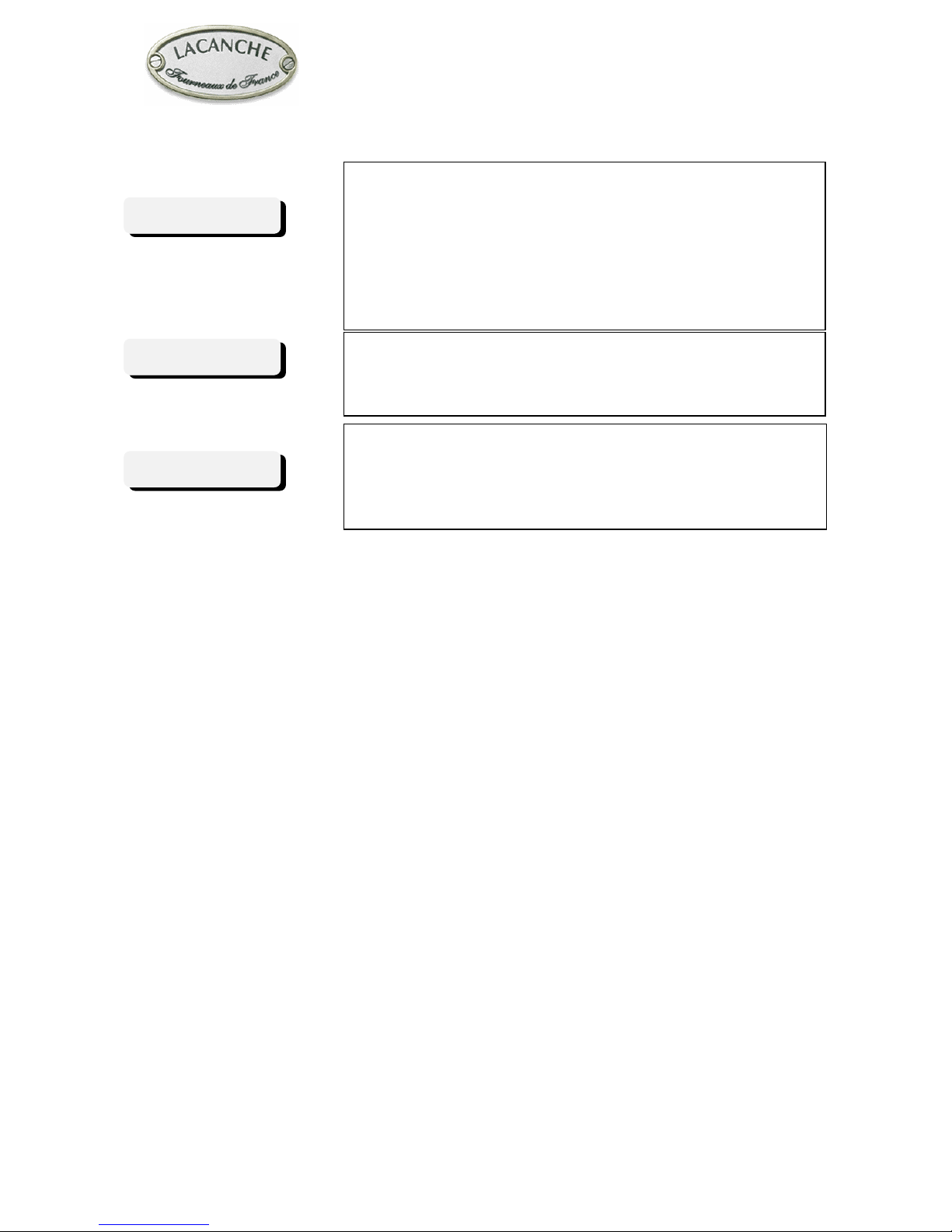
Adjusting the safety devices for each thermocouple of the hob :
If the burner goes out, having kept the control knob pushed in for roughly twenty seconds, check that :
- The magnetic head grip the valve moderately.
- The flame touches the point of thermocouple F.
- The thermocouples and magnetic heads are absolutely clean.
INSTALLER’S MANUAL
LAG 010 CKG
Page 10 sur 18– Ft010CKG – US – Date de mise à jour : 26/02/10 - Indice : 01
IMPORTANT
THE APPLIANCE MUST BE INSTALLED IN
ACCORDANCE WITH THE LOCAL CODES OR
National Fuel Gas Code, ANSI Z223.1 or latest edition.
Manual shut-off valve should be installed in an accessible
location in the gas piping external to the appliance for the
purpose of turning on or shutting off gas to the appliance.
Must be installed under an exhaust hood.
Do not install this unit near combustible walls, partitions,
pieces of furniture or decorative material unless these are
covered with adequate thermal insulation of the
noncombustible type.
Making sure the resulting installation meets fire
regulations.
IMPORTANT
IMPORTANT
Altri manuali per LAG 010 CKG
2
Indice
Altri manuali Lacanche Griglia


