LanternLITE KuroLok RL Manuale utente

FITTING INSTRUCTIONS
1

2
Drive-end headbox
Side channels x2
Side channel zip
inserts x2
Roller blind (already
inside the headbox)
You will need to use fixings suitable for the substrate you are
fixing to, these are not provided
There will also be an orange bag containing any small critical
items. This is likely to contain the controls for the blind if these
were ordered
Please unpack the delivery and check you have:
PLEASE NOTE:
THIS IS A 2+ PERSON
INSTALLATION
Spring tension-end
headbox

3
NOTE
IMPORTANT
The installation instructions in this guide should be followed otherwise the
warranty will be void.
It is the duty of the installer to pass on user and maintenance instructions to
the end user. The installer must also demonstrate the blind is fully working in
their handover to the end user.
Motorised blinds must be connected to an RCD protected circuit.
It is the installers responsibility to ensure that suitable fixings are used to
secure the blind in place
It is the installers responsibility to ensure safety is always maintained. A full
risk assessment must be carried out and documented prior to installation.
Use these instructions to fit the blind. The product has evolved slightly since
the fitting video was produced.
BEFORE INSTALLATION
If you are unsure of any element of the install, please contact us before
proceeding
All components should be checked for damage. Damaged components should
be reported to us prior to the installation beginning.

4
CTS UNIT WARNING
Please read before proceeding
This blind contains constant tension spring (CTS) units.
Take great care when pulling the cord out of the CTS! These are powerful units and can
cause damage or injury if misused!
Under NO circumstances must the cord be released to wind back into the CTS
unchecked. If this happens it WILL result in damage to the CTS and MAY ALSO result in
injury or damage to persons or property.
For your convenience and safety every CTS is provided with a locking point, which is
marked with an orange arrow. Pull the cord to rotate the spool inside the CTS until you
see the hole in the spool line up with the locking point. Insert a pin* through the locking
point into the spool to lock the CTS.
*for a locking pin you may use any metal shaft of 3-4mm diameter, e.g. small
screwdriver or screw. Ensure this does not fall inside the CTS unit.
To remove the locking pin, pull the cord tight to take the tension off the pin, lift the pin
out and allow any slack cord to SLOWLY feed back into the CTS.
In some cases your blind will be delivered with the CTS already locked with a screw
inserted into the locking point. DO NOT USE A SCREWDRIVER TO REMOVE THIS SCREW,
but remove it following the instructions above.
Locking Point
Tension Cord
NOTE

5
Fitting Options Note
There are many ways you can fit a LanternLITE™ blind. The recommended
installation method is STANDARD ORIENTATION on top of L-Profile Shelf Angle as
covered in this manual
Some of the other fixing options are shown below but should only be considered by
installers that have received training for these fitting methods.
Reverse orientation, face fix
outside the reveal
Reverse orientation, inside the
reveal
Standard orientation, side fixed
inside the reveal
Standard orientation on
aluminium batten/angle, side
fixed inside the reveal
AS SHOWN IN THIS MANUAL
NOTE

We recommend using our aluminum angle to assist installation.
If you choose not to use our aluminium angle, please be aware that the
installation will be more challenging. More time will need to be spent fine
tuning the framework to ensure the blind operates correctly.
STEP 1
6
Begin by fitting angle at the
end of the recess opening
where the roller blind and
motor will be located
This is the start of the shelf.
Offer the other 3 lengths of
angle into position and drill
fixing holes ready for these to
be fitted into place.
Do not fix these into position
yet.
NOTE
Angle/batten can be trimmed
to fit if necessary, using a
hacksaw or chop saw with a
metal cutting blade.

7
Remove the screw from each end of the
headbox containing the spring units. Keep
these screws (x2) in a safe place until the
end of the installation
STEP 2
Preparing your blind.
Remove the front cover from the tension
end by hinging up by approx. 8mm and
sliding back slightly to release it.
Leave the front cover on headbox
containing the blind.
Reverse this procedure to replace the
front cover at the end of the installation.

8
Slide the side channels onto the steel legs
of the headbox end cheeks to form a
rectangle on the floor.
STEP 3
Assembling your blind.

9
Pull out enough cord from both
CTS units to reach the roller
blind hembar + 100mm
Use a long screw or hex key to lock
the tension by inserting it into the
locking point indicated by the
sticker.
After you put this into the hole,
allow a bit of cord to go back into
the box until the tension locks
against the screw/drill bit.
Repeat for the other CTS units
Preparing the tension cords.
STEP 7
Distance to hembar + 100mm (approx.)
STEP 4
10
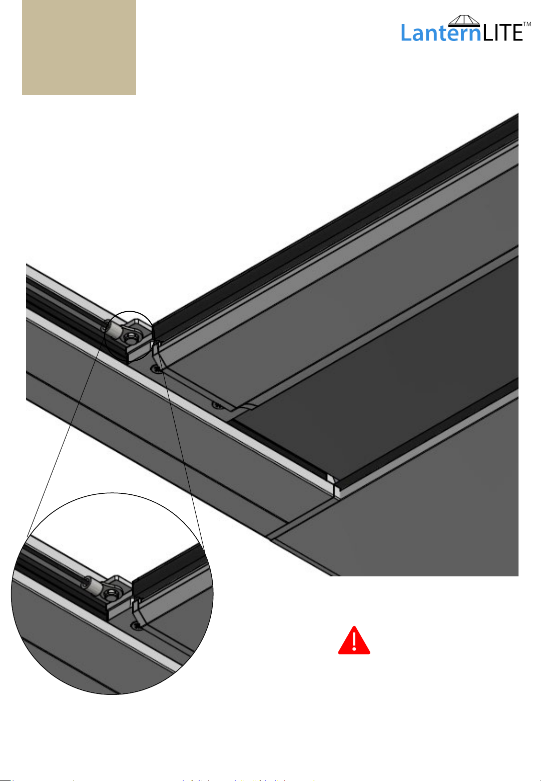
Hook the loop on the end of the cord over
the stand-off on the hembar endcap.
Do not let it fall off whilst the tension is
locked at the CTS Units
Attaching the tension cords.
STEP 5
Be careful not to let the loop drop
off whilst the cord is still slack.
Indice
Manuali Tenda per finestra popolari di altre marche


Domondo
Domondo PureNight Manuale di istruzioni per l'installazione

rollease acmeda
rollease acmeda Easy Spring Air Guida all'installazione

IKEA
IKEA KADRILJ Manuale utente

Hallis Hudson
Hallis Hudson Rolls Super glide Manuale utente

Benthin
Benthin P1614 Manuale utente

MV LINE
MV LINE CLARA 015 Manuale di istruzioni


